
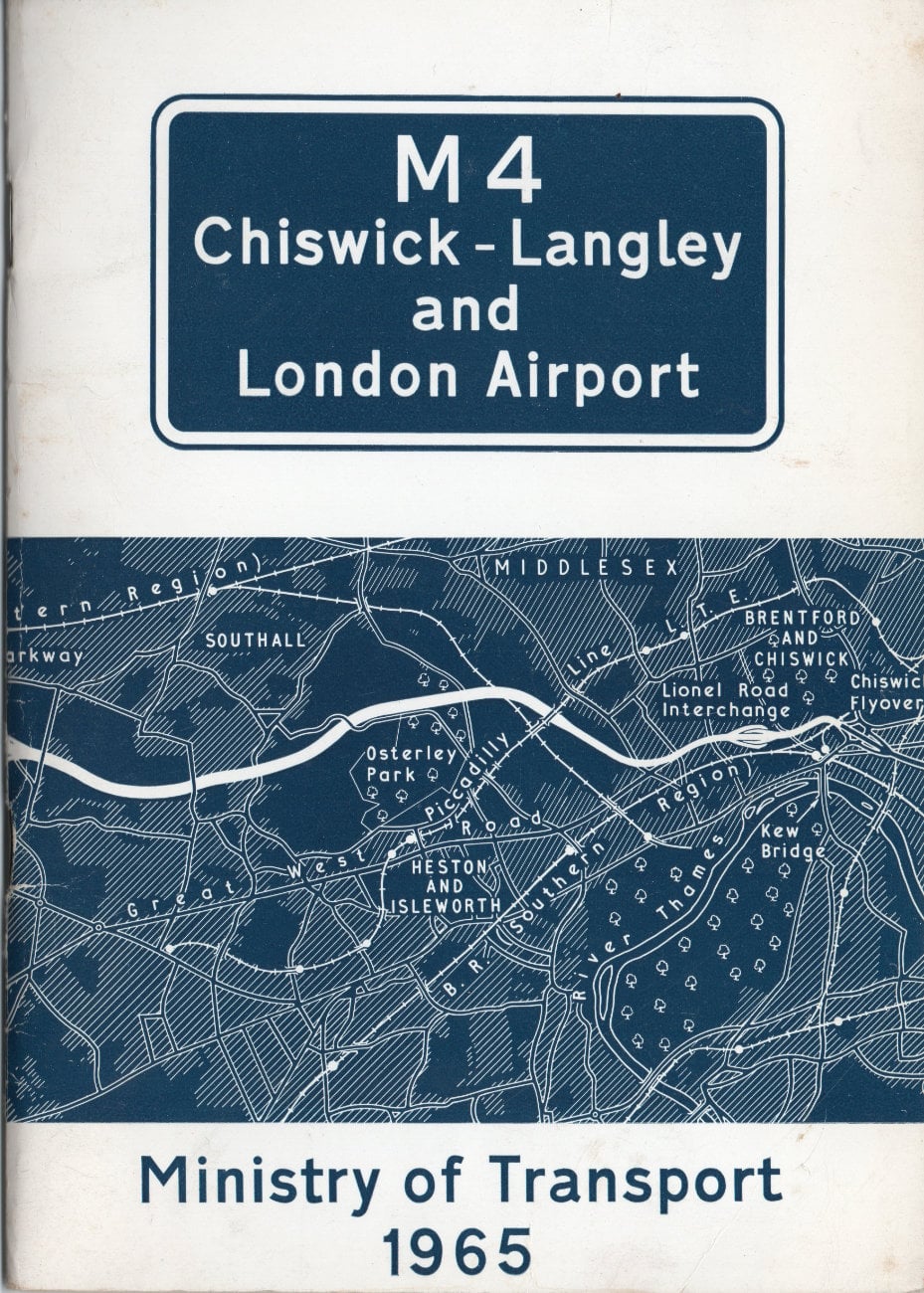
An early triumph of the motorway programme, the M4 between Chiswick and Langley linked Central London to Heathrow - then still known as London Airport - and was the start of a new motorway west.
The excitement and pride surrounding this new and pioneering length of motorway is inescapable in this booklet published to mark its opening in 1964. It included the lengthy Brentford Viaduct, carrying the motorway above the Great West Road through the suburbs, a wholly new kind of road that had never been seen before in the UK.
What its designers and builders couldn't have known was how the two-lane viaduct would quickly become a major cause of congestion on the M4, and that the bottleneck they were unwittingly creating would prove impossible to fix. But all that would come later: on opening day, all eyes were on the experimental features of the new road, its strikingly modern bridges, and the incredible feats of engineering that saw its viaduct built over the heads of passing traffic.
They might not have been right about how wide the viaduct needed to be, but they were absolutely right to be proud of a project that taught engineers and scientists a huge amount about how to build motorways - lessons that would be used as the rest of the network was built over the following decades.
Front cover
Page 1
Page 2
Page 3
Page 4
Page 5
Page 6
Page 7
Page 8
Page 9
Page 10
Page 11
Page 12
Page 13
Page 14
Page 15
Page 16
Page 17
Page 18
Page 19
Page 20
Page 21
Page 22
Page 23
Page 24
Page 25
Page 26
Page 27
Page 28
Page 29
Page 30
Page 31
Page 32
Page 33
Page 34
Page 35
Page 36
Back cover
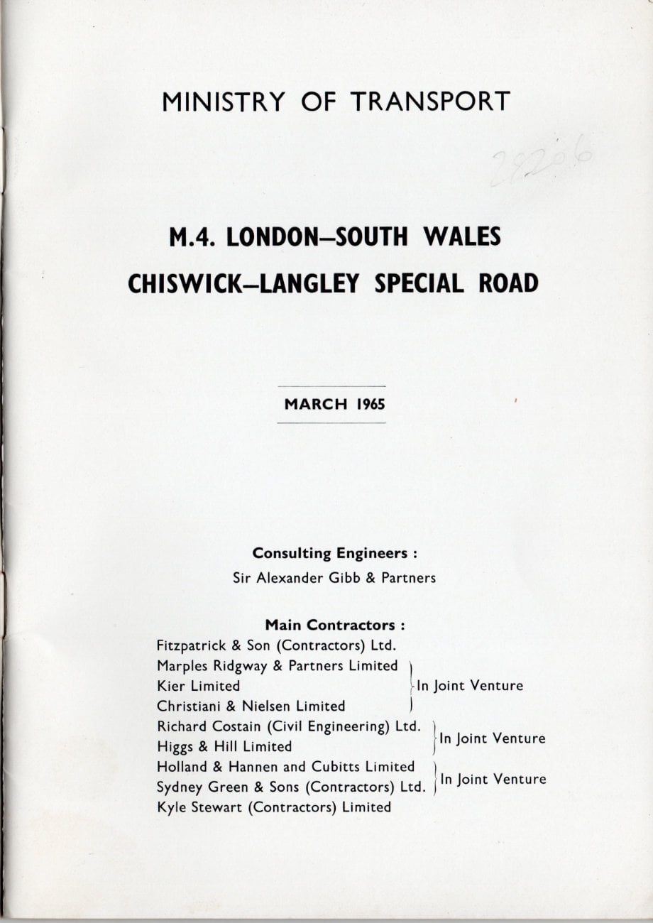
MINISTRY OF TRANSPORT
M.4. LONDON-SOUTH WALES
CHISWICK-LANGLEY SPECIAL ROAD
MARCH 1965
Consulting Engineers: Sir Alexander Gibb & Partners
Main Contractors:
| Fitzpatrick & Son (Contractors) Ltd. | |
| Marples Ridgway & Partners Limited Kier Limited Christiani & Nielsen Limited | - In Joint Venture |
| Richard Costain (Civil Engineering) Ltd. Higgs & Hill Limited | - In Joint Venture |
| Holland & Hannen and Cubitts Limited Sydney Green & Sons (Contractors) Ltd. | - In Joint Venture |
| Kyle Stewart (Contractors) Limited |
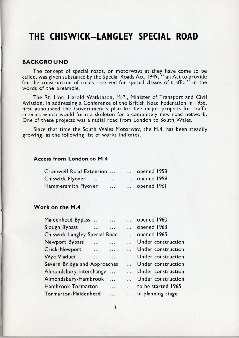
THE CHISWICK-LANGLEY SPECIAL ROAD
BACKGROUND
The concept of special roads, or motorways as they have come to be called, was given substance by the Special Roads Act, 1949, "an Act to provide for the construction of roads reserved for special classes of traffic" in the words of the preamble.
The Rt. Hon. Harold Watkinson, M.P., Minister of Transport and Civil Aviation, in addressing a Conference of the British Road Federation in 1956, first announced the Government's plan for five major projects for traffic arteries which would form a skeleton for a completely new road network. One of these projects was a radial road from London to South Wales.
Since that time the South Wales Motorway, the M.4, has been steadily growing, as the following list of works indicates.
Access from London to M.4
| Cromwell Road Extension | opened 1958 |
| Chiswick Flyover | opened 1959 |
| Hammersmith Flyover | opened 1961 |
Work on the M.4
| Maidenhead Bypass | opened 1960 |
| Slough Bypass | opened 1963 |
| Chiswick-Langley Special Road | opened 1965 |
| Newport Bypass | Under construction |
| Crick-Newport | Under construction |
| Wye Viaduct | Under construction |
| Severn Bridge and Approaches | Under construction |
| Almondsbury Interchange | Under construction |
| Almondsbury-Hambrook | Under construction |
| Hambrook-Tormarton | to be started 1965 |
| Tormarton-Maidenhead | in planning stage |
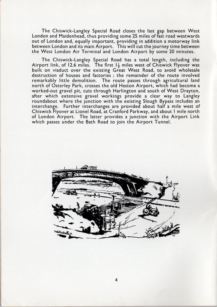
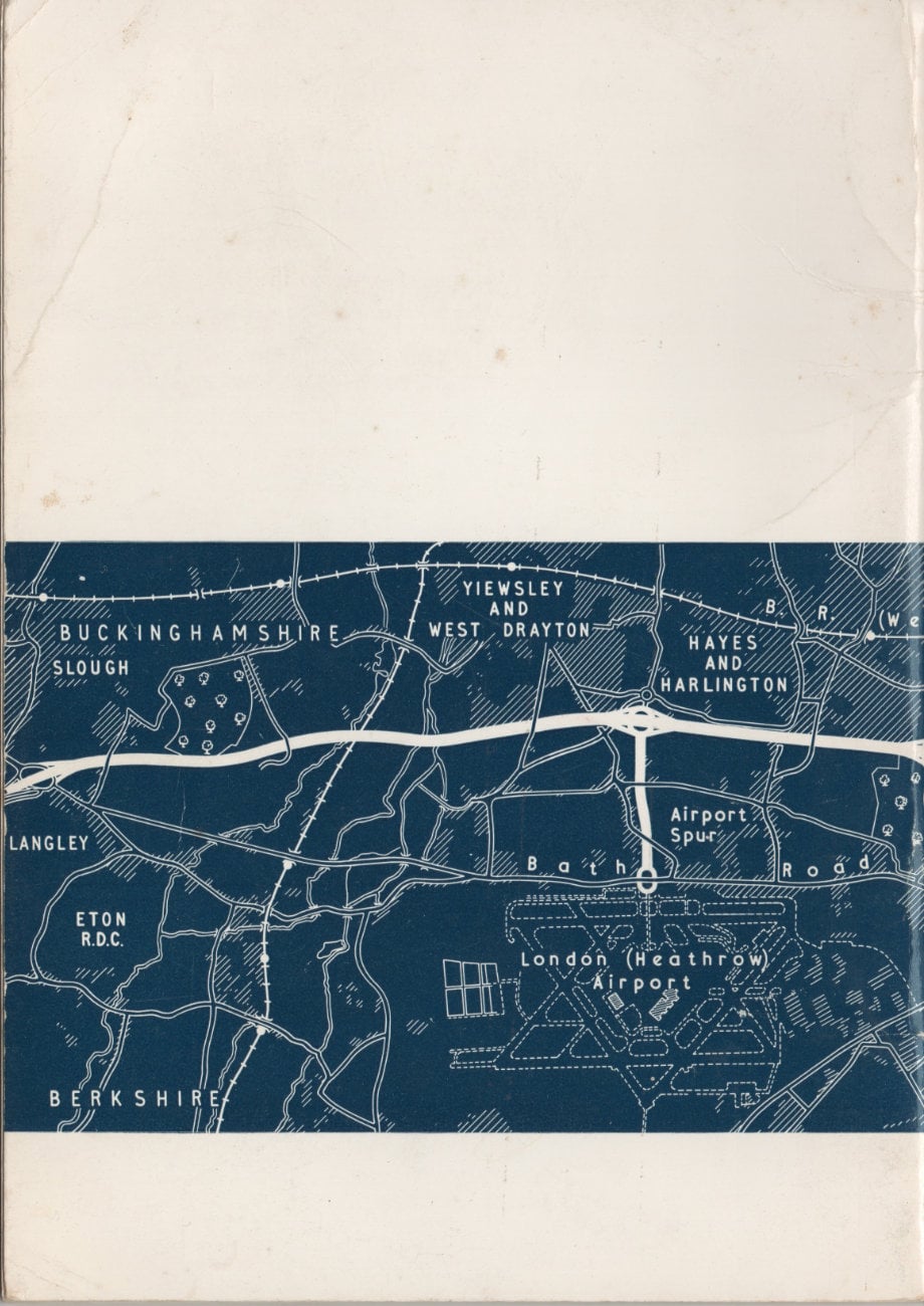
The Chiswick-Langley Special Road closes the last gap between West London and Maidenhead, thus providing some 25 miles of fast road westwards out of London and, equally important, providing in addition a motorway link between London and its main Airport. This will cut the journey time between the West London Air Terminal and London Airport by some 20 minutes.
The Chiswick-Langley Special Road has a total length, including the Airport link, of 12.6 miles. The first 1½ miles west of Chiswick Flyover was built on viaduct over the existing Great West Road, to avoid wholesale destruction of houses and factories; the remainder of the route involved remarkably little demolition. The route passes through agricultural land north of Osterley Park, crosses the old Heston Airport, which had become a worked-out gravel pit, cuts through Harlington and south of West Drayton, after which extensive gravel workings provide a clear way to Langley roundabout where the junction with the existing Slough Bypass includes an interchange. Further interchanges are provided about half a mile west of Chiswick Flyover at Lionel Road, at Cranford Parkway, and about 1 mile north of London Airport. The latter provides a junction with the Airport Link which passes under the Bath Road to join the Airport Tunnel.
PRELIMINARY WORKS (Contract 1)
Before work could commence on the viaduct section, the carriageways of the Great West Road between Chiswick Flyover and Windmill Road had to be moved outwards by 7 feet, thus increasing the width of the central reservation to 18 feet so as to provide sufficient space to construct the viaduct columns. The contract for this work was let in 1961 for completion in 15 months.
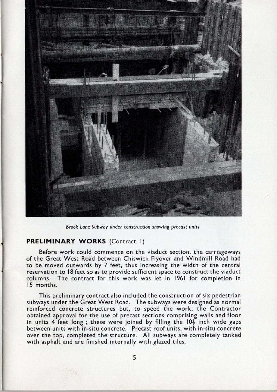
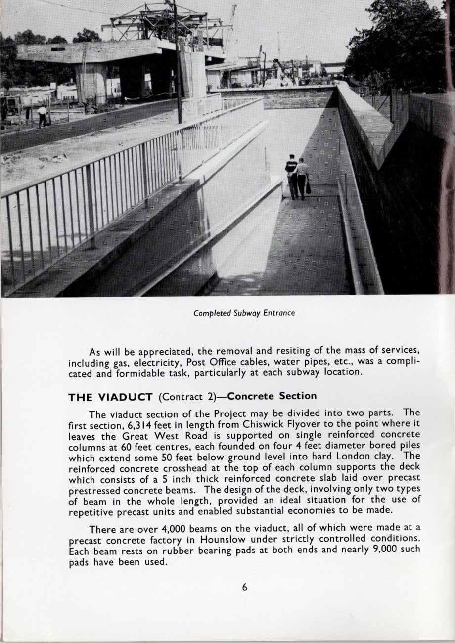
This preliminary contract also included the construction of six pedestrian subways under the Great West Road. The subways were designed as normal reinforced concrete structures but, to speed the work, the Contractor obtained approval for the use of precast sections comprising walls and floor in units 4 feet long; these were joined by filling the 10 inch wide gaps between units with in-situ concrete. Precast roof units, with in-situ concrete over the top, completed the structure. All subways are completely tanked with asphalt and are finished internally with glazed tiles.
As will be appreciated, the removal and resiting of the mass of services, including gas, electricity, Post Office cables, water pipes, etc., was a complicated and formidable task, particularly at each subway location.
THE VIADUCT (Contract 2) - Concrete Section
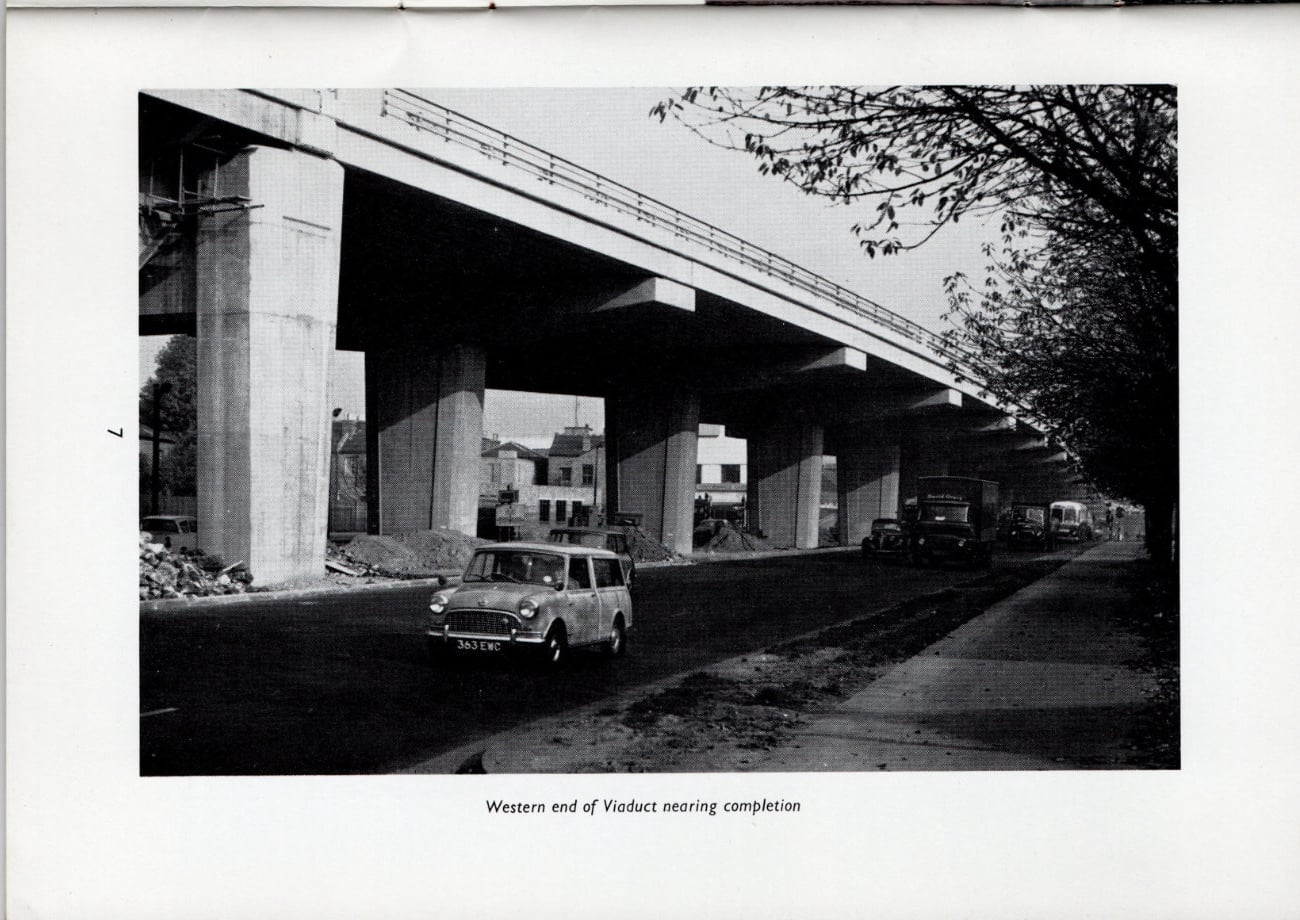
The viaduct section of the Project may be divided into two parts. The first section, 6,314 feet in length from Chiswick Flyover to the point where it leaves the Great West Road is supported on single reinforced concrete columns at 60 feet centres, each founded on four 4 feet diameter bored piles which extend some 50 feet below ground level into hard London clay. The reinforced concrete crosshead at the top of each column supports the deck which consists of a 5 inch thick reinforced concrete slab laid over precast prestressed concrete beams. The design of the deck, involving only two types of beam in the whole length, provided an ideal situation for the use of repetitive precast units and enabled substantial economies to be made.
There are over 4,000 beams on the viaduct, all of which were made at a precast concrete factory in Hounslow under strictly controlled conditions. Each beam rests on rubber bearing pads at both ends and nearly 9,000 such pads have been used.
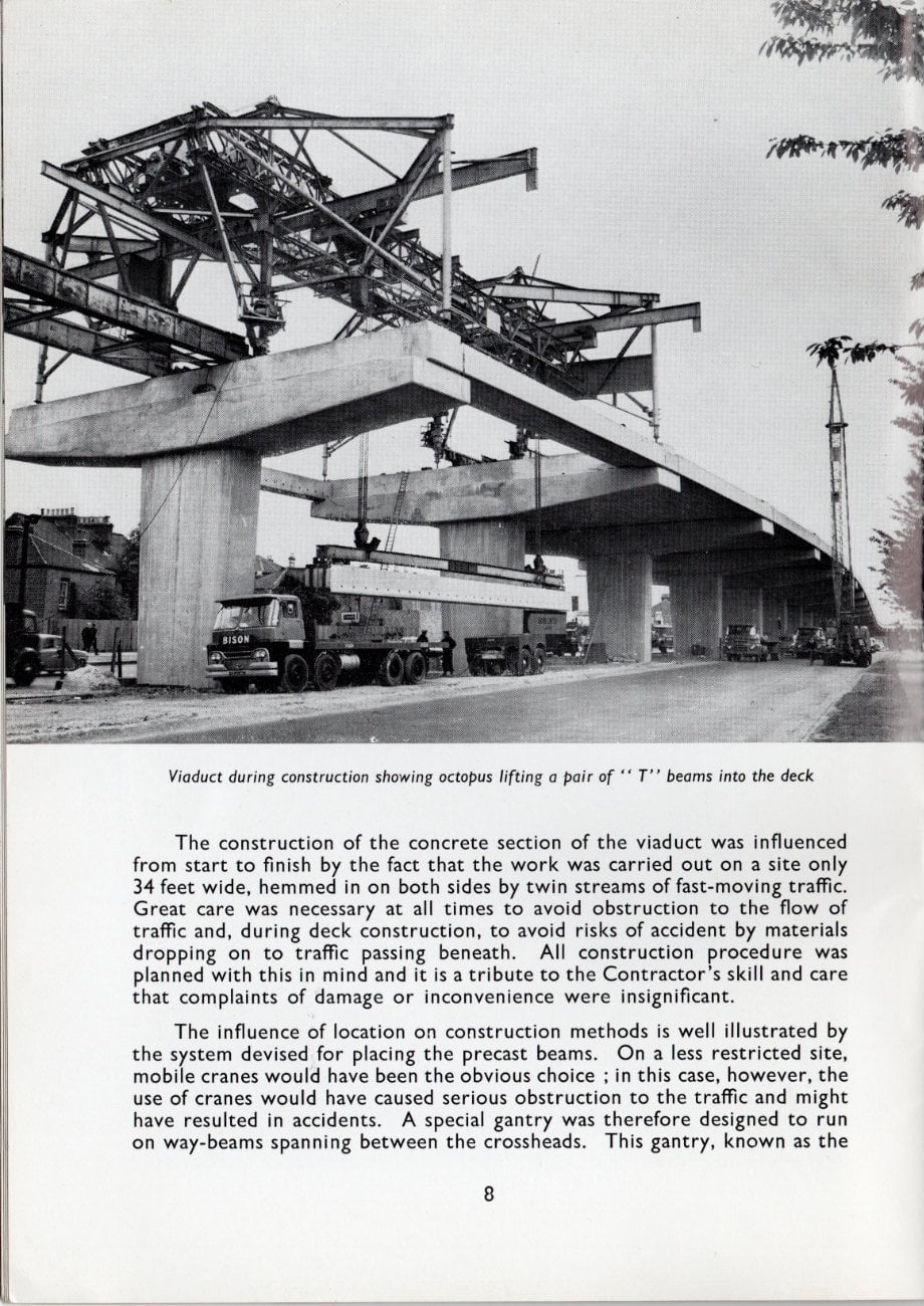
The construction of the concrete section of the viaduct was influenced from start to finish by the fact that the work was carried out on a site only 34 feet wide, hemmed in on both sides by twin streams of fast-moving traffic. Great care was necessary at all times to avoid obstruction to the flow of traffic and, during deck construction, to avoid risks of accident by materials dropping on to traffic passing beneath. All construction procedure was planned with this in mind and it is a tribute to the Contractor's skill and care that complaints of damage or inconvenience were insignificant.
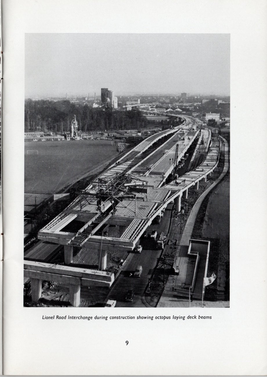
The influence of location on construction methods is well illustrated by the system devised for placing the precast beams. On a less restricted site, mobile cranes would have been the obvious choice; in this case, however, the use of cranes would have caused serious obstruction to the traffic and might have resulted in accidents. A special gantry was therefore designed to run on way-beams spanning between the crossheads. This gantry, known as the "Octopus", was able to straddle each gap in turn, supported by four legs on
each crosshead, and to lift the beams into place two at a time from the transporters which were drawn up underneath out of the traffic stream.
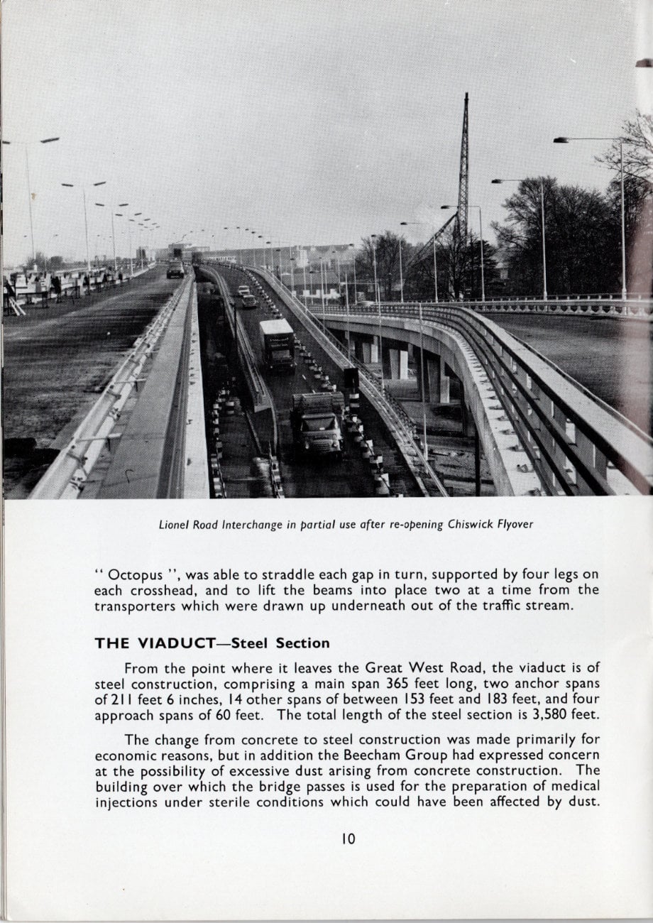
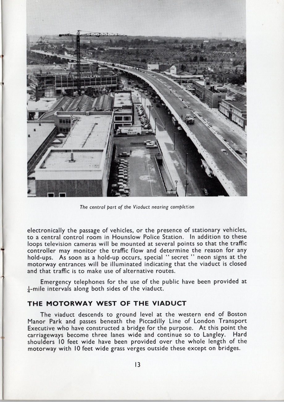
THE VIADUCT - Steel Section
From the point where it leaves the Great West Road, the viaduct is of steel construction, comprising a main span 365 feet long, two anchor spans of 211 feet 6 inches, 14 other spans of between 153 feet and 183 feet, and four approach spans of 60 feet. The total length of the steel section is 3,580 feet.
The change from concrete to steel construction was made primarily for economic reasons, but in addition the Beecham Group had expressed concern at the possibility of excessive dust arising from concrete construction. The building over which the bridge passes is used for the preparation of medical injections under sterile conditions which could have been affected by dust.
The main span, which crosses Boston Manor Road and the Beecham Group building just mentioned, together with its two anchor arms, are of welded lattice truss construction, while the remainder of the spans (excluding the approach spans) consists of four welded plate girders 8 feet deep arranged in two pairs. The design is interesting because it utilises a high yield stress steel complying with British Standard 968 which is comparatively new in this application, and introduced a number of problems in connection with welding.
A second point of interest is that the main span is built on a curve which increased considerably the design problems in dealing with the resulting stress distribution.
With the exception of the main and approach span supports, the steel viaduct is carried on a series of twin reinforced concrete columns, supported in turn on bored piles similar to those under the concrete section. The main span is supported on large concrete caissons which were sunk into the ground by excavating material from the inside. These caissons eventually came to rest on hard London clay about 45 feet below ground level.
The deck of the steel section is a reinforced concrete slab 7½ inches thick carried on transverse steel girders spaced at a little over 7 feet apart. Temporary support for the concrete deck was eliminated by using thin precast prestressed concrete planks spanning between the transverse girders and left in position as part of the structure. This method greatly speeded the deck construction.
CARRIAGEWAYS ON THE VIADUCT (both sections)
The viaduct has an overall width throughout of 60 feet, comprising two 24 feet wide carriageways, a 4 feet wide central reservation, and 4 feet wide verges.
After making up crossfalls where necessary with bitumen bound base-course the whole of the deck was waterproofed with a ¾ inch layer of mastic asphalt. Heating cables, to which further reference is made below, were laid on the mastic and these were covered over with a 7/8 inch thick course of sand asphalt. The carriageways were completed by a wearing course of hot rolled asphalt 1¾ inch thick.
To accommodate expansion of the steel viaduct, open joints have been provided at the ends of each section. The carriageways are carried over the joints by means of meehanite cast iron plates with intermeshing teeth. On the concrete section, the provision of such plates at 60 feet intervals would have adversely affected the riding quality of the road and would also have been very expensive. The anticipated movement was about ¼ inch which, if not catered for, would have caused unsightly cracks in the asphalt surfacing and permitted water to penetrate through the deck. The problem was solved by carrying the mastic asphalt waterproof layer across the joint by means of strips of P.V.C. water seal. The surfacing is carried straight across the joint and in order to pre-determine the position of any propagated cracks, a groove 3/8 inch wide and ½ inch deep has been sawn in the road surface over each joint and filled with a rubber bitumen compound.
Steel safety fences have been provided down both sides of each carriageway and on the outer edges of the viaduct a steel balustrade gives additional protection. A further precaution in the form of road heating to prevent ice formation is described later.
Gulleys are provided every 60 feet at the low side of each carriageway. On the concrete section these discharge into 4 inch drain pipes passing down the columns and on the steel section they discharge into 9 inch diameter steel headers running beneath the deck.
ROAD HEATING
In view of the greater risk of frost formation on an elevated structure and the possibly serious consequences of vehicles skidding into the barriers, road heating has been installed throughout the length of the viaduct and on the slip roads of the Lionel Road interchange. The use of mineral insulated copper sheathed cables for the heating element provided increased protection against damage during installation. The cables are laid in grid pattern 6 inches apart to form panels 12 feet wide and 20 feet long. Each panel has a consumption of 3 kilowatts and the total electrical load for the whole viaduct is about 8,000 kilowatts. Leads from the panels are terminated in fuse boxes in the central reservation and the supply comes from sub-stations placed at intervals under the viaduct.
It is important that the heating system should be switched on in good time if there is any danger of frost, and special detectors have been installed in the road surface at intervals. These automatically bring the system into use as soon as the temperature of the road surface nears freezing point and provided moisture is present in addition. Thus the heating will remain off in conditions of dry cold, but as soon as frost begins to form or snow to lie, these conditions are detected and the heating system automatically comes into operation.
There are over 200 miles of cable in the heating panels alone, and many miles more have been installed for the distribution and control systems. This is the biggest road heating installation in this country at the present time.
TRAFFIC CONTROL
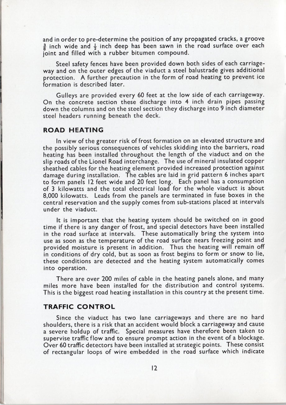
Since the viaduct has two lane carriageways and there are no hard shoulders, there is a risk that an accident would block a carriageway and cause a severe holdup of traffic. Special measures have therefore been taken to supervise traffic flow and to ensure prompt action in the event of a blockage. Over 60 traffic detectors have been installed at strategic points. These consist of rectangular loops of wire embedded in the road surface which indicate electronically the passage of vehicles, or the presence of stationary vehicles, to a central control room in Hounslow Police Station. In addition to these loops television cameras will be mounted at several points so that the traffic controller may monitor the traffic flow and determine the reason for any hold-ups. As soon as a hold-up occurs, special "secret" neon signs at the motorway entrances will be illuminated indicating that the viaduct is closed and that traffic is to make use of alternative routes.
Emergency telephones for the use of the public have been provided at ¼-mile intervals along both sides of the viaduct.
THE MOTORWAY WEST OF THE VIADUCT
The viaduct descends to ground level at the western end of Boston Manor Park and passes beneath the Piccadilly Line of London Transport Executive who have constructed a bridge for the purpose. At this point the carriageways become three lanes wide and continue so to Langley. Hard shoulders 10 feet wide have been provided over the whole length of the motorway with 10 feet wide grass verges outside these except on bridges.
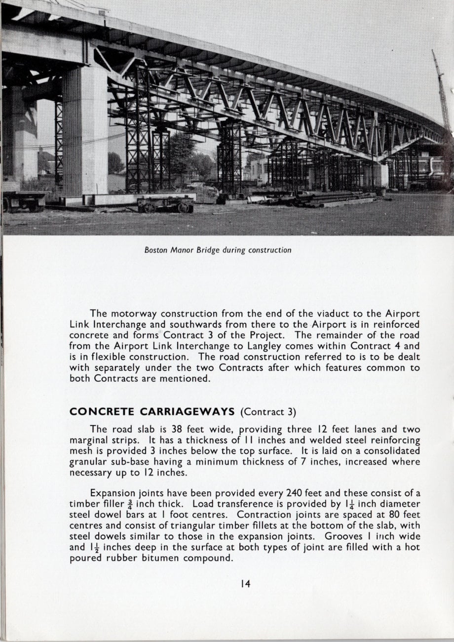
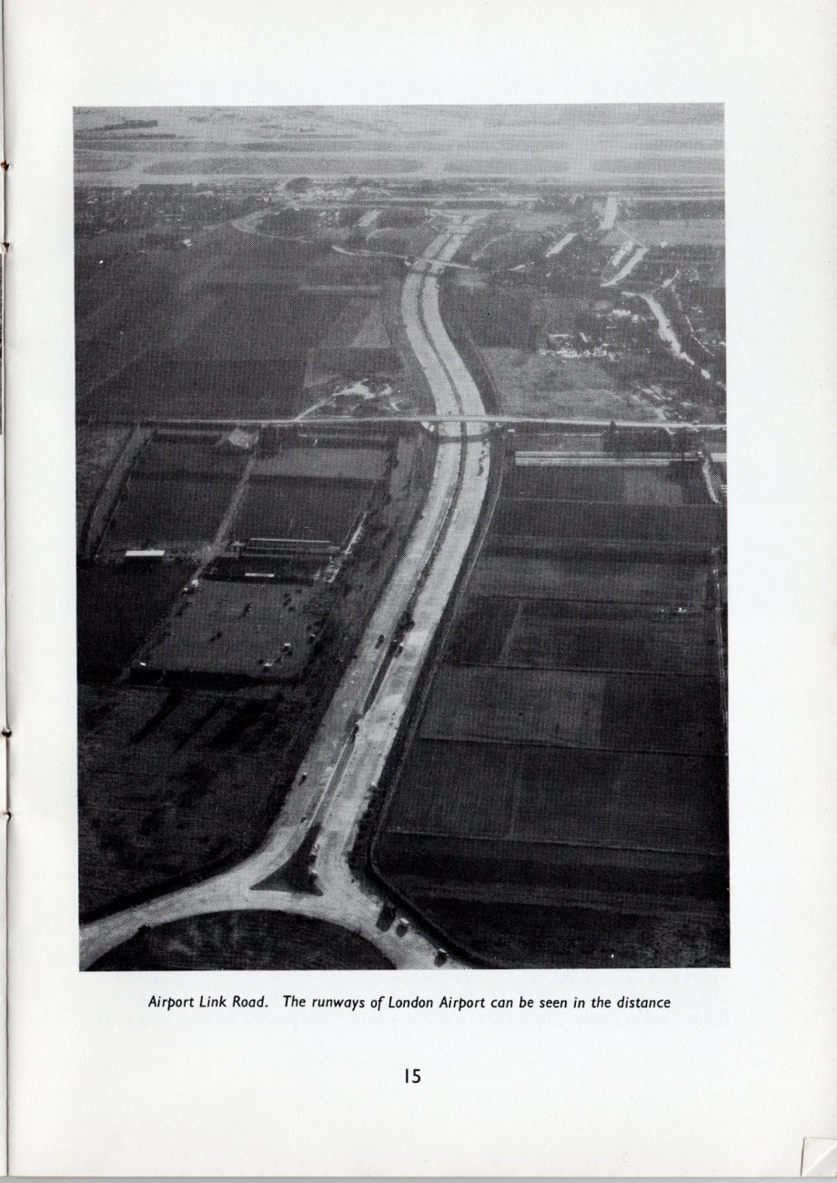
The motorway construction from the end of the viaduct to the Airport Link Interchange and southwards from there to the Airport is in reinforced concrete and forms Contract 3 of the Project. The remainder of the road from the Airport Link Interchange to Langley comes within Contract 4 and is in flexible construction. The road construction referred to is to be dealt with separately under the two Contracts after which features common to both Contracts are mentioned.
CONCRETE CARRIAGEWAYS (Contract 3)
The road slab is 38 feet wide, providing three 12 feet lanes and two marginal strips. It has a thickness of 11 inches and welded steel reinforcing mesh is provided 3 inches below the top surface. It is laid on a consolidated granular sub-base having a minimum thickness of 7 inches, increased where necessary up to 12 inches.
Expansion joints have been provided every 240 feet and these consist of a timber filler ¾ inch thick. Load transference is provided by 1¼ inch diameter steel dowel bars at 1 foot centres. Contraction joints are spaced at 80 feet centres and consist of triangular timber fillets at the bottom of the slab, with steel dowels similar to those in the expansion joints. Grooves 1 inch wide and 14 inches deep in the surface at both types of joint are filled with a hot poured rubber bitumen compound.
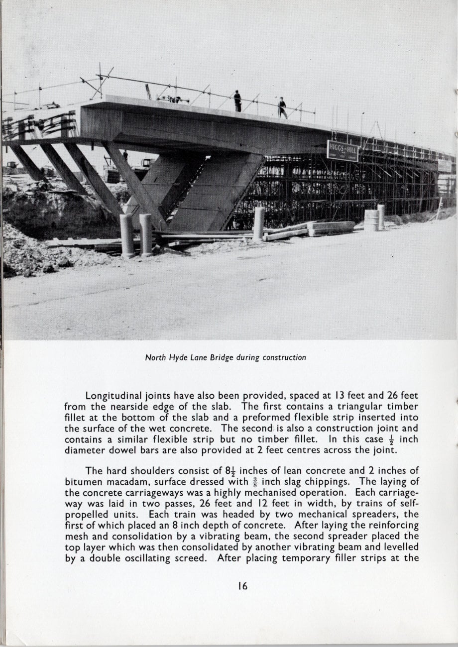
Longitudinal joints have also been provided, spaced at 13 feet and 26 feet from the nearside edge of the slab. The first contains a triangular timber fillet at the bottom of the slab and a preformed flexible strip inserted into the surface of the wet concrete. The second is also a construction joint and contains a similar flexible strip but no timber fillet. In this case ½ inch diameter dowel bars are also provided at 2 feet centres across the joint.
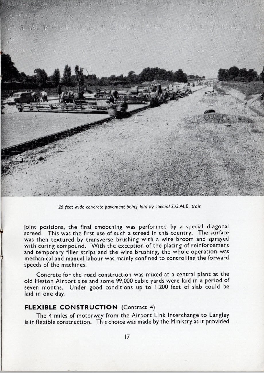
The hard shoulders consist of 8½ inches of lean concrete and 2 inches of bitumen macadam, surface dressed with 1 inch slag chippings. The laying of the concrete carriageways was a highly mechanised operation. Each carriageway was laid in two passes, 26 feet and 12 feet in width, by trains of self-propelled units. Each train was headed by two mechanical spreaders, the first of which placed an 8 inch depth of concrete. After laying the reinforcing mesh and consolidation by a vibrating beam, the second spreader placed the top layer which was then consolidated by another vibrating beam and levelled by a double oscillating screed. After placing temporary filler strips at the joint positions, the final smoothing was performed by a special diagonal screed. This was the first use of such a screed in this country. The surface was then textured by transverse brushing with a wire broom and sprayed with curing compound. With the exception of the placing of reinforcement and temporary filler strips and the wire brushing, the whole operation was mechanical and manual labour was mainly confined to controlling the forward speeds of the machines.
Concrete for the road construction was mixed at a central plant at the old Heston Airport site and some 99,000 cubic yards were laid in a period of seven months. Under good conditions up to 1,200 feet of slab could be laid in one day.
FLEXIBLE CONSTRUCTION (Contract 4)
The 4 miles of motorway from the Airport Link Interchange to Langley is in flexible construction. This choice was made by the Ministry as it provided an excellent opportunity to assess, in conjunction with the Road Research Laboratory, the behaviour of various types of flexible base laid under normal contract conditions and at the same time to compare the overall behaviour of flexible construction with the concrete construction of Contract 3.
Each carriageway was therefore divided into sections, providing seven trial lengths and the following bases were laid.
- 10 inches bitumen bound gravel base on 6 inches min. sub-base.
- 6 inches hot rolled asphalt (rock) on 10 inches min. sub-base.
- 8 inches hot rolled asphalt (rock) on 8 inches min. sub-base.
- 10 inches hot rolled asphalt (gravel) on 6 inches min. sub-base.
- 10 inches tar bound base (rock) on 6 inches min. sub-base.
- 3 inches bitumen bound base (rock) on 7 inches lean concrete on 6 inches sub-base.
- 3 inches tar bound base (rock) on 7 inches lean concrete on 6 inches sub-base.
The sub-base in all cases was gravel conforming to Type 2 of the Ministry of Transport Specification.
The minimum thickness of sub-base could not in all cases be adhered to since poor ground conditions in places demanded greater thicknesses. Some areas were stabilised with cement to assist winter working.
The surfacing did not vary and consisted throughout of 1½ inches of hot rolled asphalt with crushed rock aggregate (30 per cent. stone content) on 2½ inches of hot rolled asphalt with 60 per cent. gravel content. Coated chippings having a polished stone coefficient of 0.60 were rolled into the surface at a rate of about 130 square yards per ton.
The dry lean concrete was laid with Blaw Knox PF90 pavers and the bituminous materials with Barber-Greene S.A.40 machines. The lean concrete was obtained from a Parker plant fitted with a ground hopper and conveyor and was purpose built for the Contract. The bituminous and tarbound materials were manufactured in a plant built on site by the surfacing sub-contractor. Separate blacktop laboratories controlled by the sub-contractor and the Engineer respectively ensured close control of the materials.
The hard shoulders on Contract 4 are of similar construction to those on Contract 3, i.e., surface dressing on 2 inches of bitumen base course on lean concrete, the thickness of which in this case varies according to the thickness of the adjacent carriageway construction.
EARTHWORKS (Contracts 3 and 4)
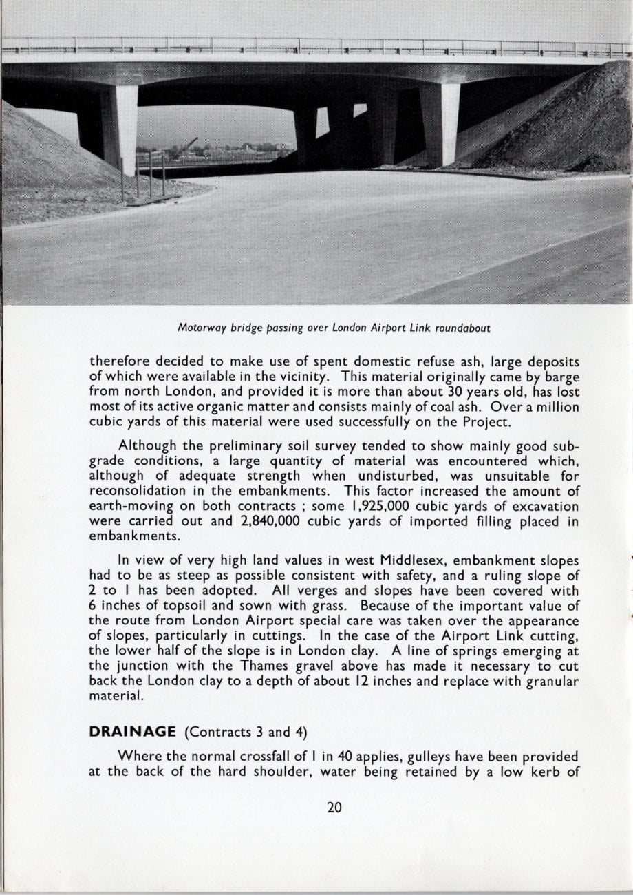
Under the conditions imposed by the semi-urban nature of the route, it was inevitable that a great deal of filling material would be required for embankments over and above that which could be obtained from cuttings. This is difficult to obtain at reasonable cost in West London and it was therefore decided to make use of spent domestic refuse ash, large deposits of which were available in the vicinity. This material originally came by barge from north London, and provided it is more than about 30 years old, has lost most of its active organic matter and consists mainly of coal ash. Over a million cubic yards of this material were used successfully on the Project.
Although the preliminary soil survey tended to show mainly good sub-grade conditions, a large quantity of material was encountered which, although of adequate strength when undisturbed, was unsuitable for reconsolidation in the embankments. This factor increased the amount of earth-moving on both contracts; some 1,925,000 cubic yards of excavation were carried out and 2,840,000 cubic yards of imported filling placed in embankments.
In view of very high land values in west Middlesex, embankment slopes had to be as steep as possible consistent with safety, and a ruling slope of 2 to 1 has been adopted. All verges and slopes have been covered with 6 inches of topsoil and sown with grass. Because of the important value of the route from London Airport special care was taken over the appearance of slopes, particularly in cuttings. In the case of the Airport Link cutting, the lower half of the slope is in London clay. A line of springs emerging at the junction with the Thames gravel above has made it necessary to cut back the London clay to a depth of about 12 inches and replace with granular material.
DRAINAGE (Contracts 3 and 4)
Where the normal crossfall of 1 in 40 applies, gulleys have been provided at the back of the hard shoulder, water being retained by a low kerb of extruded asphalt. On super-elevated sections, gulleys are provided in the central reserve. Gulleys discharge into longitudinal drains or ditches as appropriate and french drains have been provided on both sides in cuttings as well as in the central reservation at super-elevated sections.
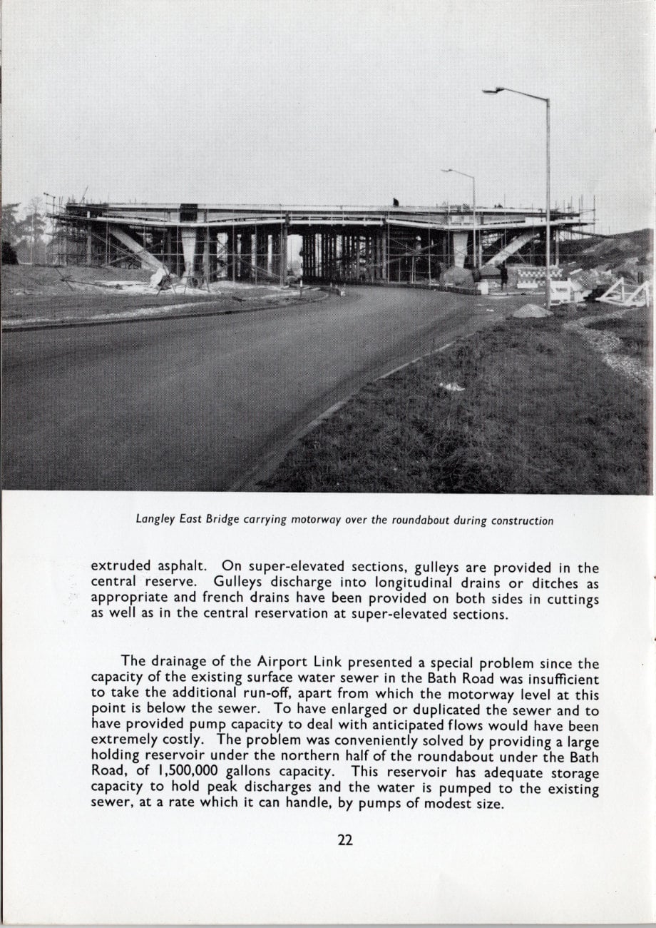
The drainage of the Airport Link presented a special problem since the capacity of the existing surface water sewer in the Bath Road was insufficient to take the additional run-off, apart from which the motorway level at this point is below the sewer. To have enlarged or duplicated the sewer and to have provided pump capacity to deal with anticipated flows would have been extremely costly. The problem was conveniently solved by providing a large holding reservoir under the northern half of the roundabout under the Bath Road, of 1,500,000 gallons capacity. This reservoir has adequate storage capacity to hold peak discharges and the water is pumped to the existing sewer, at a rate which it can handle, by pumps of modest size.
MARGINAL STRIPS (Contracts 3 and 4)
The Ministry of Transport, in conjunction with the Road Research Laboratory, have made use of a number of different marginal strips in order to compare their respective visibility and durability.
The following types are represented:
- Thermoplastic line.
- Surface dressed calcined flint chippings.
- Calcined flint chippings worked into the fresh concrete.
- White concrete inlay.
- White paint with a strip of ballotini.
- White plastic tiles.
- Plain concrete blocks.
- Ribbed concrete blocks.
- Concrete blocks with calcined flint exposed aggregate surface.
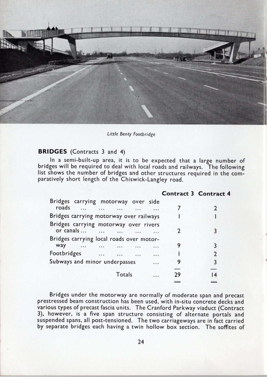
BRIDGES (Contracts 3 and 4)
In a semi-built-up area, it is to be expected that a large number of bridges will be required to deal with local roads and railways. The following list shows the number of bridges and other structures required in the comparatively short length of the Chiswick-Langley road.
| Contract 3 | Contract 4 | |
|---|---|---|
| Bridges carrying motorway over side roads | 7 | 2 |
| Bridges carrying motorway over railways | 1 | 1 |
| Bridges carrying motorway over rivers or canals | 2 | 3 |
| Bridges carrying local roads over motorway | 9 | 3 |
| Footbridges | 1 | 2 |
| Subways and minor underpasses | 9 | 3 |
| Totals | 29 | 14 |
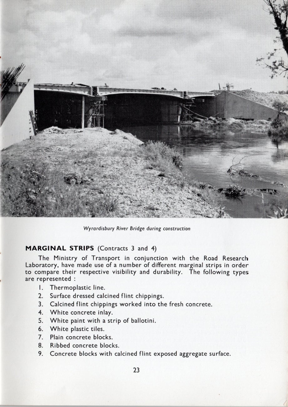
Bridges under the motorway are normally of moderate span and precast prestressed beam construction has been used, with in-situ concrete decks and various types of precast fascia units. The Cranford Parkway viaduct (Contract 3), however, is a five span structure consisting of alternate portals and suspended spans, all post-tensioned. The two carriageways are in fact carried by separate bridges each having a twin hollow box section. The soffites of the bridges and the lower part of the deck slabs are precast concrete panels, while the webs, diaphragms, and upper part of the deck slabs are of in-situ concrete construction.
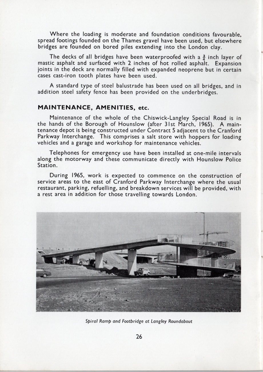
The two bridges carrying the motorway over Langley roundabout (Contract 4) are also of twin hollow box construction and consist of separate bridges for each carriageway. The principle of separate bridges has in fact been generally adopted for underbridges.
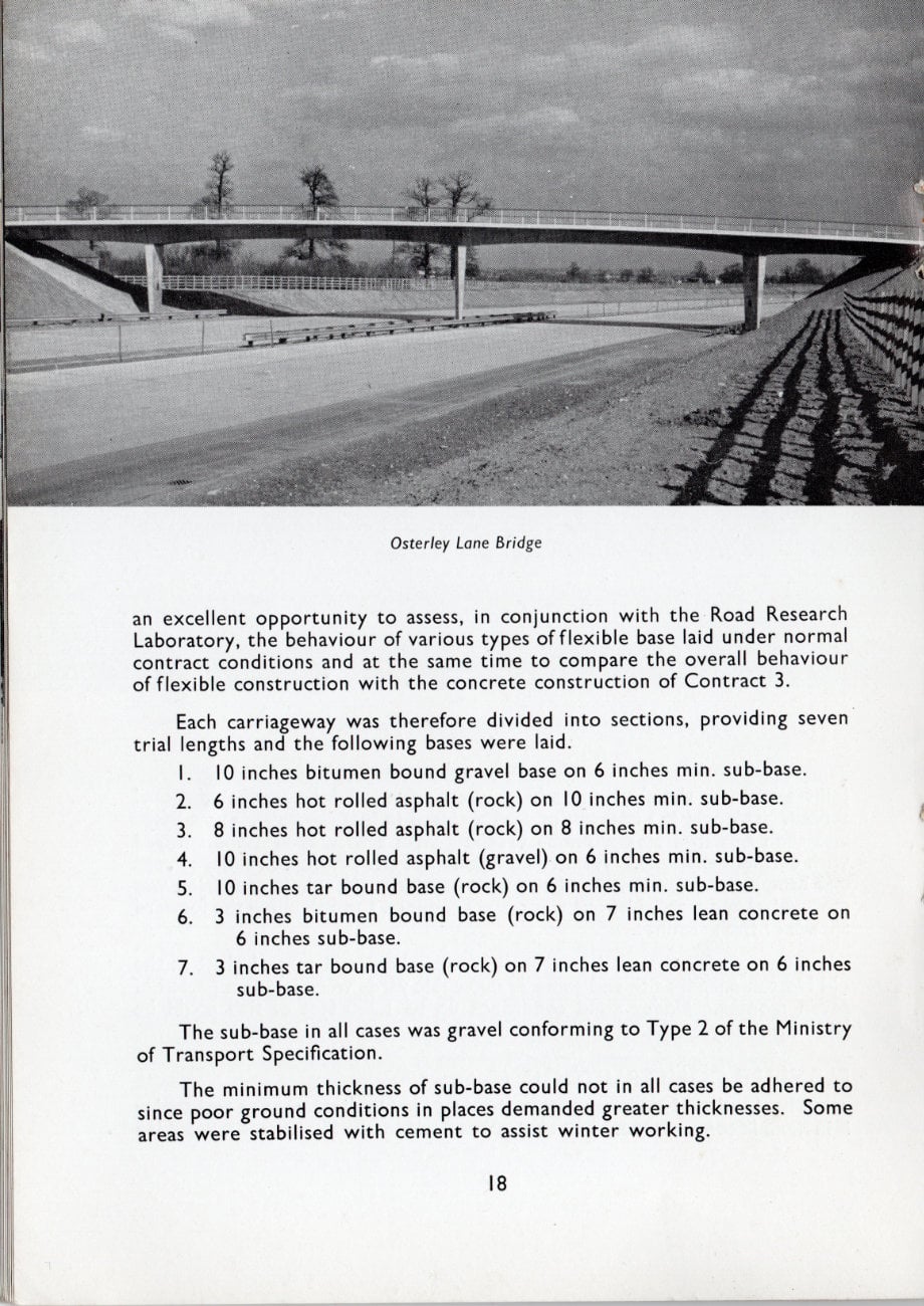
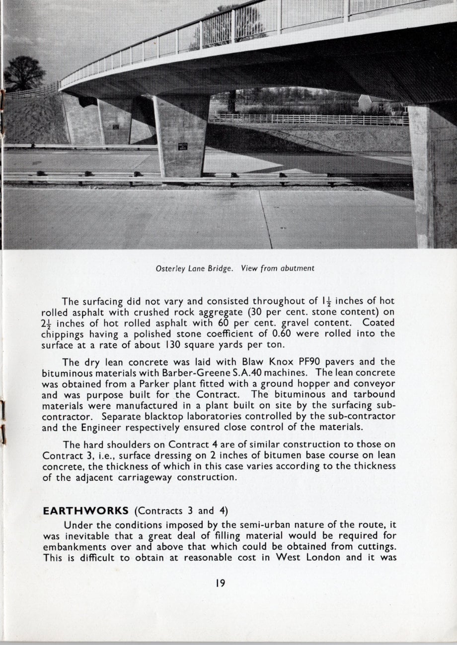
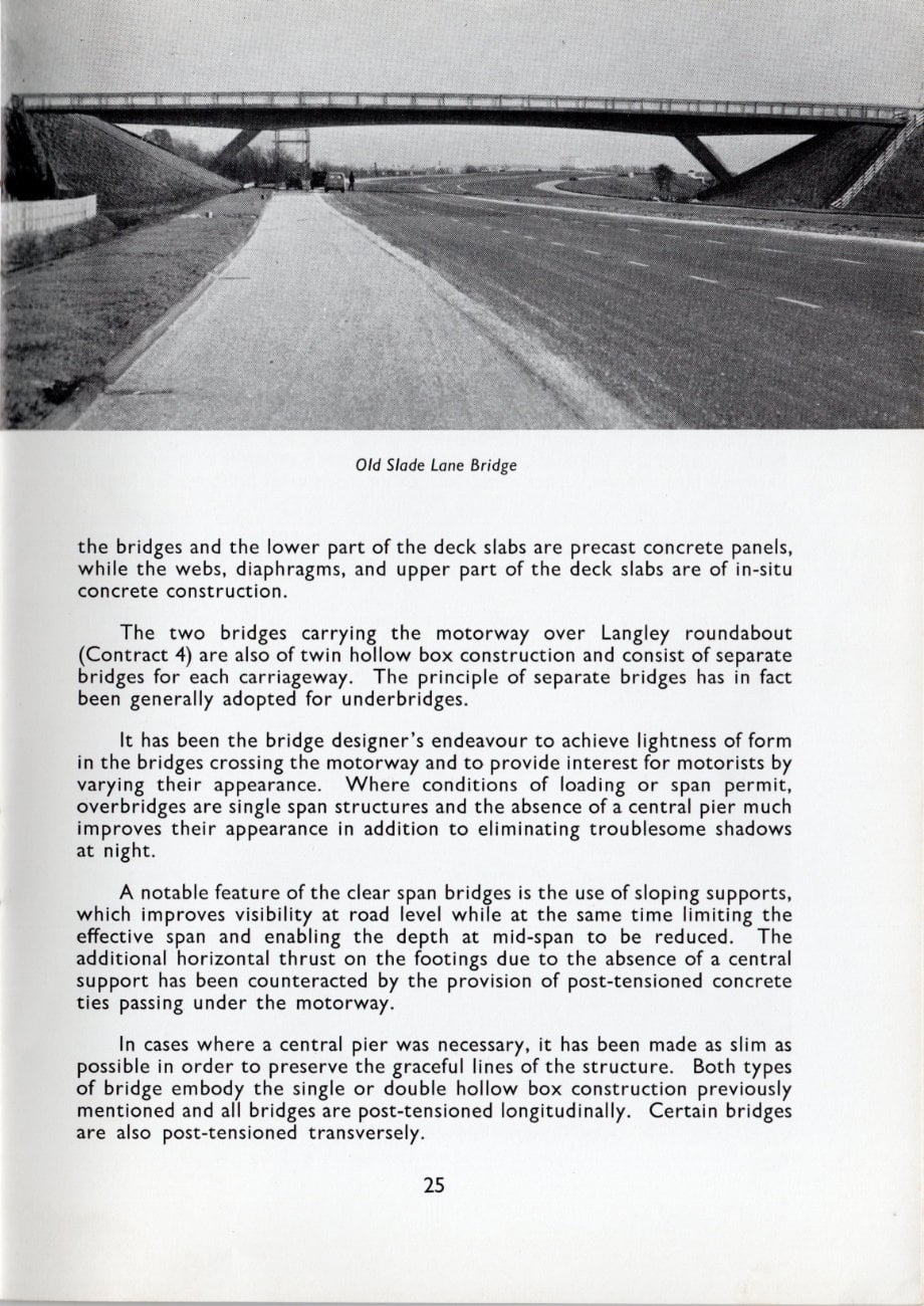
It has been the bridge designer's endeavour to achieve lightness of form in the bridges crossing the motorway and to provide interest for motorists by varying their appearance. Where conditions of loading or span permit, overbridges are single span structures and the absence of a central pier much improves their appearance in addition to eliminating troublesome shadows at night.
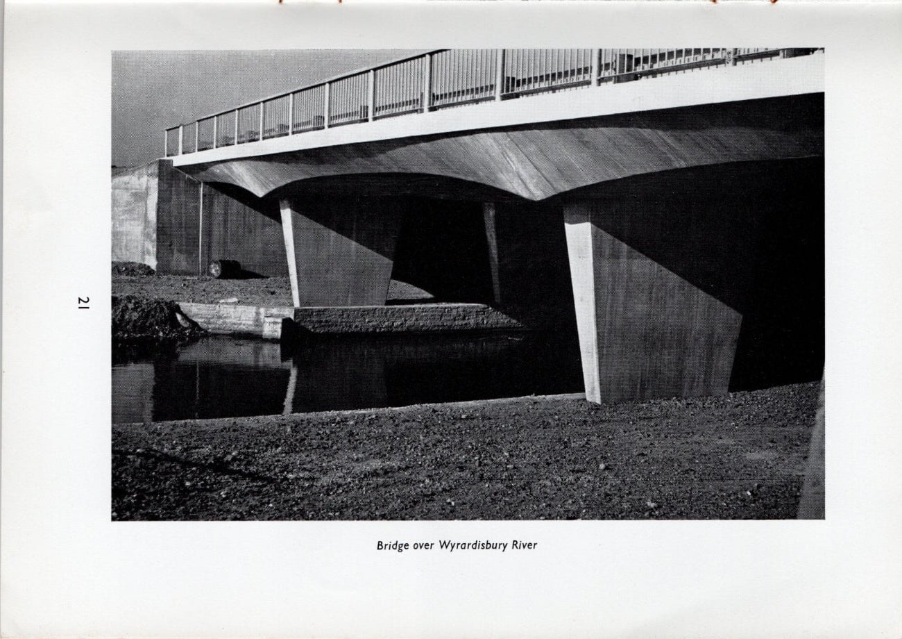
A notable feature of the clear span bridges is the use of sloping supports, which improves visibility at road level while at the same time limiting the effective span and enabling the depth at mid-span to be reduced. The additional horizontal thrust on the footings due to the absence of a central support has been counteracted by the provision of post-tensioned concrete ties passing under the motorway.
In cases where a central pier was necessary, it has been made as slim as possible in order to preserve the graceful lines of the structure. Both types of bridge embody the single or double hollow box construction previously mentioned and all bridges are post-tensioned longitudinally. Certain bridges are also post-tensioned transversely.
Where the loading is moderate and foundation conditions favourable, spread footings founded on the Thames gravel have been used, but elsewhere bridges are founded on bored piles extending into the London clay.
The decks of all bridges have been waterproofed with a ¾ inch layer of mastic asphalt and surfaced with 2 inches of hot rolled asphalt. Expansion joints in the deck are normally filled with expanded neoprene but in certain cases cast-iron tooth plates have been used.
A standard type of steel balustrade has been used on all bridges, and in addition steel safety fence has been provided on the underbridges.
MAINTENANCE, AMENITIES, etc.
Maintenance of the whole of the Chiswick-Langley Special Road is in the hands of the Borough of Hounslow (after 31st March, 1965). A maintenance depot is being constructed under Contract 5 adjacent to the Cranford Parkway Interchange. This comprises a salt store with hoppers for loading vehicles and a garage and workshop for maintenance vehicles.
Telephones for emergency use have been installed at one-mile intervals along the motorway and these communicate directly with Hounslow Police Station.
During 1965, work is expected to commence on the construction of service areas to the east of Cranford Parkway Interchange where the usual restaurant, parking, refuelling, and breakdown services will be provided, with a rest area in addition for those travelling towards London.
ACKNOWLEDGMENTS
The Consulting Engineers wish to express their appreciation and thanks for the valuable assistance given to them from the inception of the scheme to completion of this major and complicated section of motor road by all the officers of the Ministry of Transport. Special mention must be made in this connection of the advice and encouragement received from Mr. J. F. A. Baker C.B., M.I.C.E., M.I.Mun. E., Director of Highway Engineering; Mr. J. G. Smith, M.I.C.E., M.I.Mun.E., F.Inst.H.E., Chief Highways Engineer; and Mr. J. D. W. Jeffery, T.D., M.I.C.E., recently retired.
The Engineers are grateful for the help and co-operation of the County Engineers and officials of Middlesex, Berkshire, and Buckinghamshire, and in particular would mention Mr. H. S. Andrew, M.I.C.E., M.I.Mun.E., County Engineer of Middlesex. Much assistance was received from the four Borough Councils, two Urban District Councils and one Rural District Council in whose areas the work was carried out, also from the Service Authorities, Road Research Laboratories, and the Cement and Concrete Association.
The contribution of Mr. Harry Brompton, M.I.C.E., M.I.Struct. E., M..W.E., in modifying his designs for the Chiswick Flyover to facilitate its later junction with the Viaduct merits special recognition.
Without the invaluable advice and constant vigilance of the Police, the freedom from traffic jams and the absence of serious accidents despite the unending stream of traffic beneath the works on the viaduct section and elsewhere could not have been achieved: from the Scotland Yard Traffic Branch to each man on the beat we offer our grateful thanks.
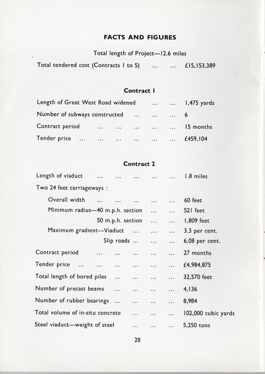
FACTS AND FIGURES
Total length of Project: 12.6 miles
Total tendered cost (Contracts 1 to 5): £15,153,389
Contract 1
| Length of Great West Road widened | 1,475 yards |
| Number of subways constructed | 6 |
| Contract period | 15 months |
| Tender price | £459,104 |
Contract 2
| Length of viaduct | 1.8 miles | |
| Two 24 feet carriageways: | Overall width | 60 feet |
| Minimum radius - 40 m.p.h. section | 521 feet | |
| Minimum radius - 50 m.p.h. section | 1,809 feet | |
| Maximum gradient - Viaduct | 3.3 per cent. | |
| Maximum gradient - Slip roads | 6.08 per cent. | |
| Contract period | 27 months | |
| Tender price | £4,984,875 | |
| Total length of bored piles | 32,570 feet | |
| Number of precast beams | 4,136 | |
| Number of rubber bearings | 8,984 | |
| Total volume of in-situ concrete | 102,000 cubic yards | |
| Steel viaduct - weight of steel | 5,250 tons | |
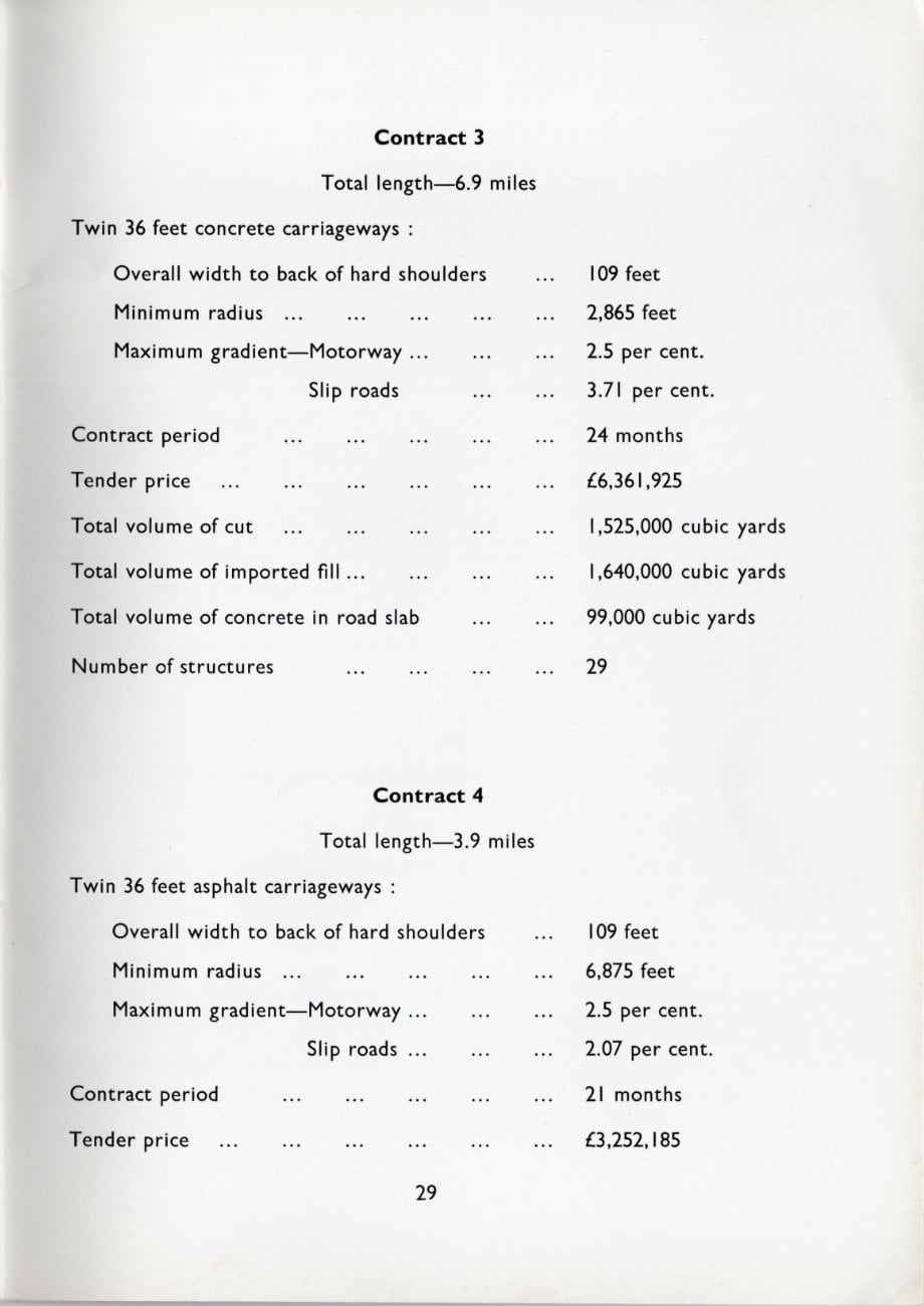
Contract 3
| Total length | 6.9 miles | |
| Twin 36 feet concrete carriageways: | Overall width to back of hard shoulders | 109 feet |
| Minimum radius | 2,865 feet | |
| Maximum gradient - Motorway | 2.5 per cent. | |
| Maximum gradient - Slip roads | 3.71 per cent. | |
| Contract period | 24 months | |
| Tender price | £6,361,925 | |
| Total volume of cut | 1,525,000 cubic yards | |
| Total volume of imported fill | 1,640,000 cubic yards | |
| Total volume of concrete in road slab | 99,000 cubic yards | |
| Number of structures | 29 | |
Contract 4
| Total length | 3.9 miles | |
| Twin 36 feet asphalt carriageways: | Overall width to back of hard shoulders | 109 feet |
| Minimum radius | 6,875 feet | |
| Maximum gradient - Motorway | 2.5 per cent. | |
| Maximum gradient - Slip roads | 2.07 per cent. | |
| Contract period | 21 months | |
| Tender price | £3,252,185 | |
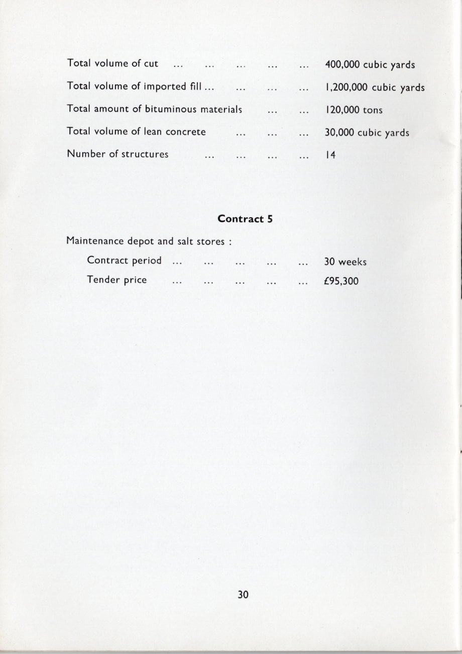
| Total volume of cut | 400,000 cubic yards | |
| Total volume of imported fill | 1,200,000 cubic yards | |
| Total amount of bituminous materials | 120,000 tons | |
| Total volume of lean concrete | 30,000 cubic yards | |
| Number of structures | 14 | |
Contract 5
Maintenance depot and salt stores:
| Contract period | 30 weeks |
| Tender price | £95,300 |
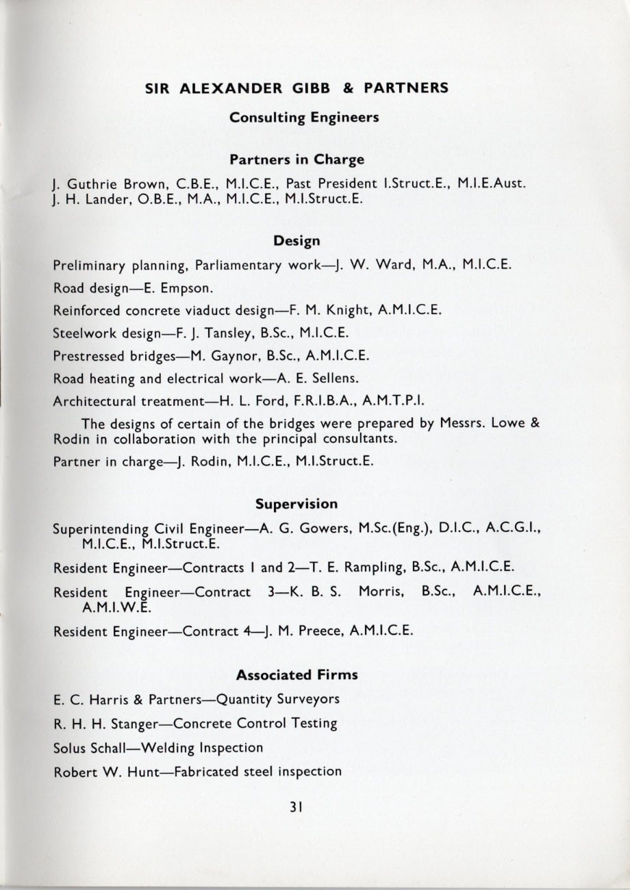
SIR ALEXANDER GIBB & PARTNERS
Consulting Engineers
Partners in Charge
- J. Guthrie Brown, C.B.E., M.I.C.E., Past President I.Struct. E., M.I.E.Aust
- J. H. Lander, O.B.E., M.A., M.I.C.E., M.I.Struct.E
Design
- Preliminary planning, Parliamentary work - J. W. Ward, M.A., M.I.C.E.
- Road design - E. Empson.
- Reinforced concrete viaduct design - F. M. Knight, A.M.I.C.E.
- Steelwork design - F. J. Tansley, B.Sc., M.I.C.E.
- Prestressed bridges - M. Gaynor, B.Sc., A.M.I.C.E.
- Road heating and electrical work - A. E. Sellens.
- Architectural treatment - H. L. Ford, F.R.I.B.A., A.M.T.P.I.
- The designs of certain of the bridges were prepared by Messrs. Lowe & Rodin in collaboration with the principal consultants.
- Partner in charge J. Rodin, M.I.C.E., M.I.Struct. E.
Supervision
- Superintending Civil Engineer - A. G. Gowers, M.Sc. (Eng.), D.I.C., A.C.G.I., M.I.C.E., M.I.Struct.E.
- Resident Engineer - Contracts 1 and 2 - T. E. Rampling, B.Sc., A.M.I.C.E.
- Resident Engineer - Contract 3 - K. B. S. Morris, B.Sc., A.M.I.C.E., A.M.I.W.E.
- Resident Engineer - Contract 4 - J. M. Preece, A.M.I.C.E.
Associated Firms
- E. C. Harris & Partners - Quantity Surveyors
- R. H. H. Stanger - Concrete Control Testing
- Solus Schall - Welding Inspection
- Robert W. Hunt - Fabricated steel inspection
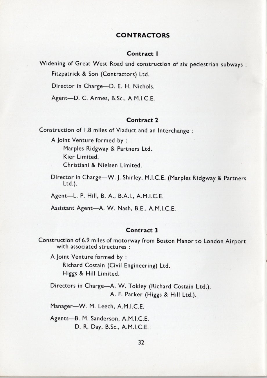
CONTRACTORS
Contract 1
Widening of Great West Road and construction of six pedestrian subways:
- Fitzpatrick & Son (Contractors) Ltd.
- Director in Charge - D. E. H. Nichols.
- Agent - D. C. Armes, B.Sc., A.M.I.C.E.
Contract 2
Construction of 1.8 miles of Viaduct and an Interchange:
- A Joint Venture formed by:
- Marples Ridgway & Partners Ltd.
- Kier Limited
- Christiani & Nielsen Limited.
- Director in Charge - W. J. Shirley, M.I.C.E. (Marples Ridgway & Partners Ltd.).
- Agent - L. P. Hill, B. A., B.A.I., A.M.I.C.E.
- Assistant Agent - A. W. Nash, B.E., A.M.I.C.E.
Contract 3
Construction of 6.9 miles of motorway from Boston Manor to London Airport with associated structures:
- A Joint Venture formed by:
- Richard Costain (Civil Engineering) Ltd.
- Higgs & Hill Limited.
- Directors in Charge
- A. W. Tokley (Richard Costain Ltd.).
- A. F. Parker (Higgs & Hill Ltd.).
- Manager - W. M. Leech, A.M.I.C.E.
- Agents
- B. M. Sanderson, A.M.I.C.E.
- D. R. Day, B.Sc., A.M.I.C.E.
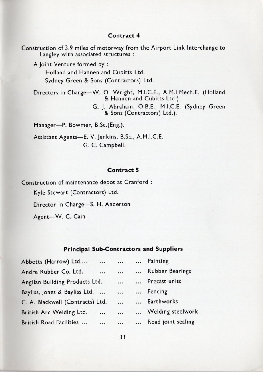
Contract 4
Construction of 3.9 miles of motorway from the Airport Link Interchange to Langley with associated structures:
- A Joint Venture formed by:
- Holland and Hannen and Cubitts Ltd.
- Sydney Green & Sons (Contractors) Ltd.
- Directors in Charge
- W. O. Wright, M.I.C.E., A.M.I.Mech.E. (Holland & Hannen and Cubitts Ltd.)
- G. J. Abraham, O.B.E., M.I.C.E. (Sydney Green & Sons (Contractors) Ltd.).
- Manager - P. Bowmer, B.Sc. (Eng.).
- Assistant Agents
- E. V. Jenkins, B.Sc., A.M.I.C.E.
- G. C. Campbell.
Contract 5
Construction of maintenance depot at Cranford:
- Kyle Stewart (Contractors) Ltd.
- Director in Charge - S. H. Anderson
- Agent - W. C. Cain
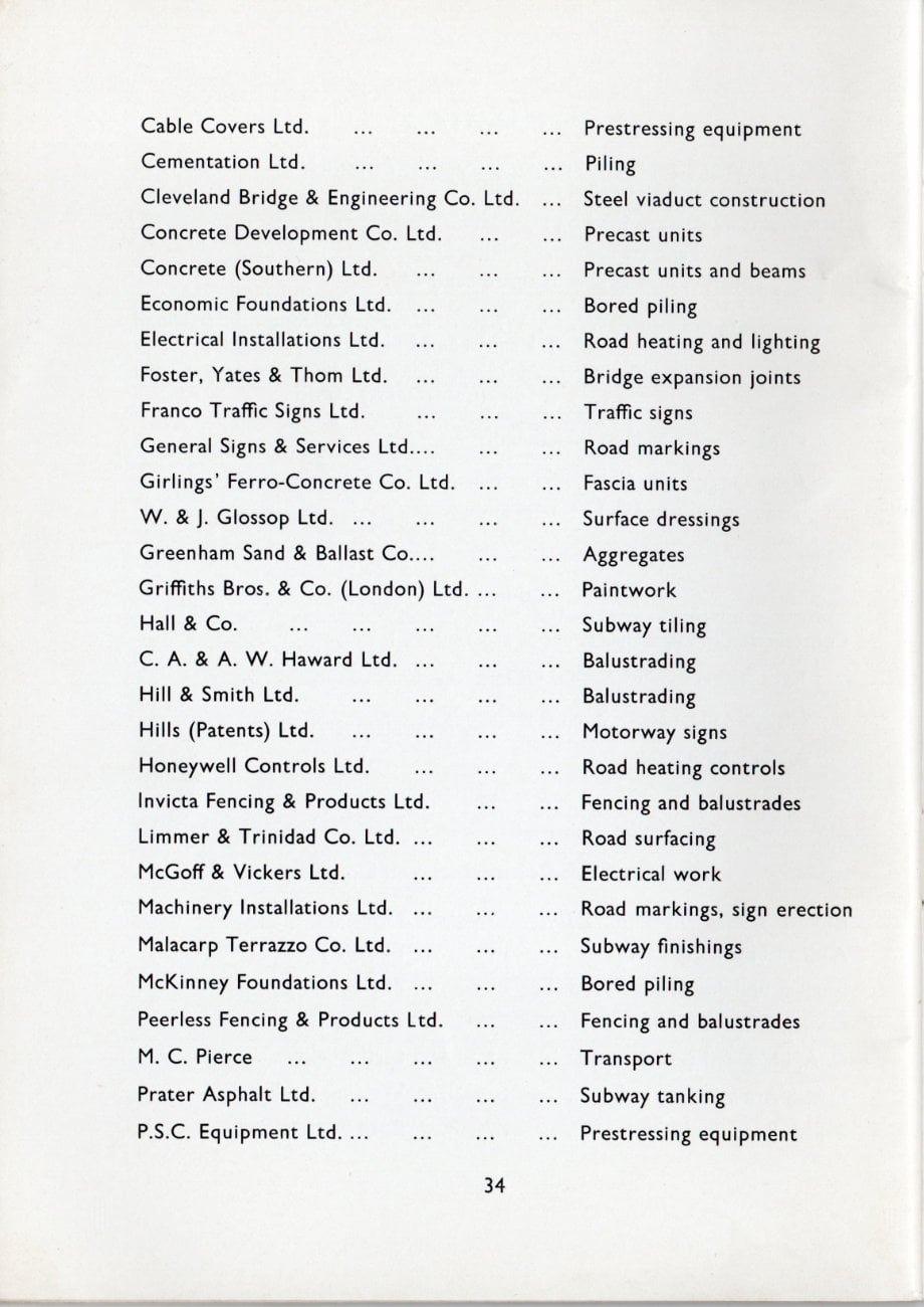
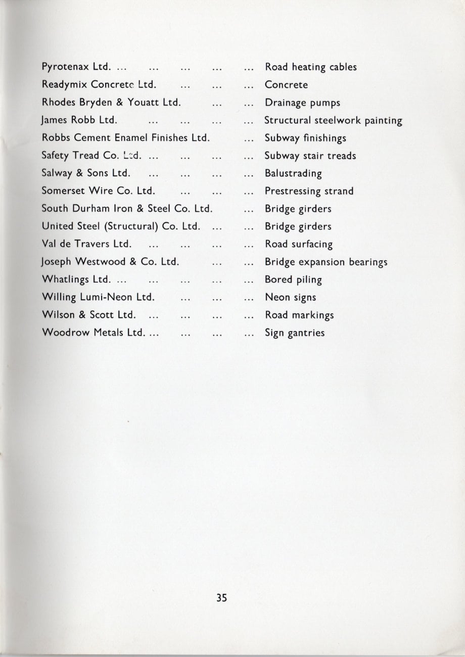
Principal Sub-Contractors and Suppliers
| Abbotts (Harrow) Ltd | Painting |
| Andre Rubber Co. Ltd. | Rubber Bearings |
| Anglian Building Products Ltd. | Precast units |
| Bayliss, Jones & Bayliss Ltd. | Fencing |
| C. A. Blackwell (Contracts) Ltd. | Earthworks |
| British Arc Welding Ltd. | Welding steelwork |
| British Road Facilities | Road joint sealing |
| Cable Covers Ltd. | Prestressing equipment |
| Cementation Ltd. | Piling |
| Cleveland Bridge & Engineering Co. Ltd. | Steel viaduct construction |
| Concrete Development Co. Ltd. | Precast units |
| Concrete (Southern) Ltd. | Precast units and beams |
| Economic Foundations Ltd. | Bored piling |
| Electrical Installations Ltd. | Road heating and lighting |
| Foster, Yates & Thom Ltd. | Bridge expansion joints |
| Franco Traffic Signs Ltd. | Traffic signs |
| General Signs & Services Ltd. | Road markings |
| Girlings' Ferro-Concrete Co. Ltd. | Fascia units |
| W. & J. Glossop Ltd. | Surface dressings |
| Greenham Sand & Ballast Co... | Aggregates |
| Griffiths Bros. & Co. (London) Ltd. | Paintwork |
| Hall & Co. | Subway tiling |
| C. A. & A. W. Haward Ltd. | Balustrading |
| Hill & Smith Ltd. | Balustrading |
| Hills (Patents) Ltd. | Motorway signs |
| Honeywell Controls Ltd. | Road heating controls |
| Invicta Fencing & Products Ltd. | Fencing and balustrades |
| Limmer & Trinidad Co. Ltd. | Road surfacing |
| McGoff & Vickers Ltd. | Electrical work |
| Machinery Installations Ltd. | Road markings, sign erection |
| Malacarp Terrazzo Co. Ltd. | Subway finishings |
| McKinney Foundations Ltd. | Bored piling |
| Peerless Fencing & Products Ltd. | Fencing and balustrades |
| M. C. Pierce | Transport |
| Prater Asphalt Ltd. | Subway tanking |
| P.S.C. Equipment Ltd. | Prestressing equipment |
| Pyrotenax Ltd. | Road heating cables |
| Readymix Concrete Ltd. | Concrete |
| Rhodes Bryden & Youatt Ltd. | Drainage pumps |
| James Robb Ltd. | Structural steelwork painting |
| Robbs Cement Enamel Finishes Ltd. | Subway finishings |
| Safety Tread Co. Ltd. | Subway stair treads |
| Salway & Sons Ltd. | Balustrading |
| Somerset Wire Co. Ltd. | Prestressing strand |
| South Durham Iron & Steel Co. Ltd. | Bridge girders |
| United Steel (Structural) Co. Ltd. | Bridge girders |
| Val de Travers Ltd. | Road surfacing |
| Joseph Westwood & Co. Ltd. | Bridge expansion bearings |
| Whatlings Ltd. | Bored piling |
| Willing Lumi-Neon Ltd. | Neon signs |
| Wilson & Scott Ltd. | Road markings |
| Woodrow Metals Ltd. | Sign gantries |
Comments
Like what he said.

Great leaflet - it's a shame it isn't a pdf that could be downloaded and read at leisure!