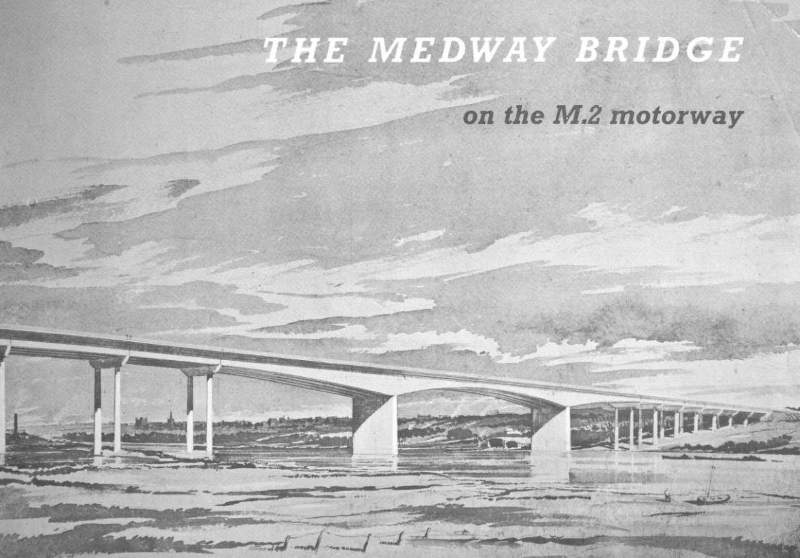
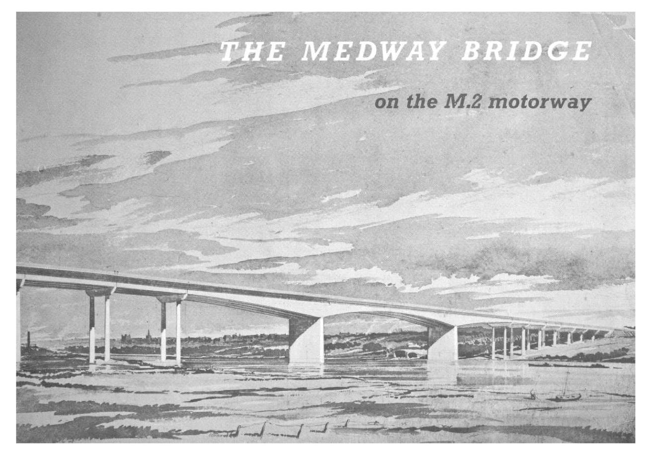
The Medway Motorway, or Medway Towns Bypass, was opened in around 1965 as a handy way to get past Chatham, Gillingham and Rochester. The whole of the M2 was pretty much one big project, and these two booklets commemorate the opening of the road itself and the Medway Bridge, its major engineering feature.
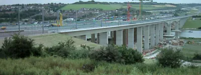
The motorway's western end was upgraded out of all recognition from these documents in the early 2000s, and the Medway Bridge itself was duplicated with a near-identical copy to widen the motorway.
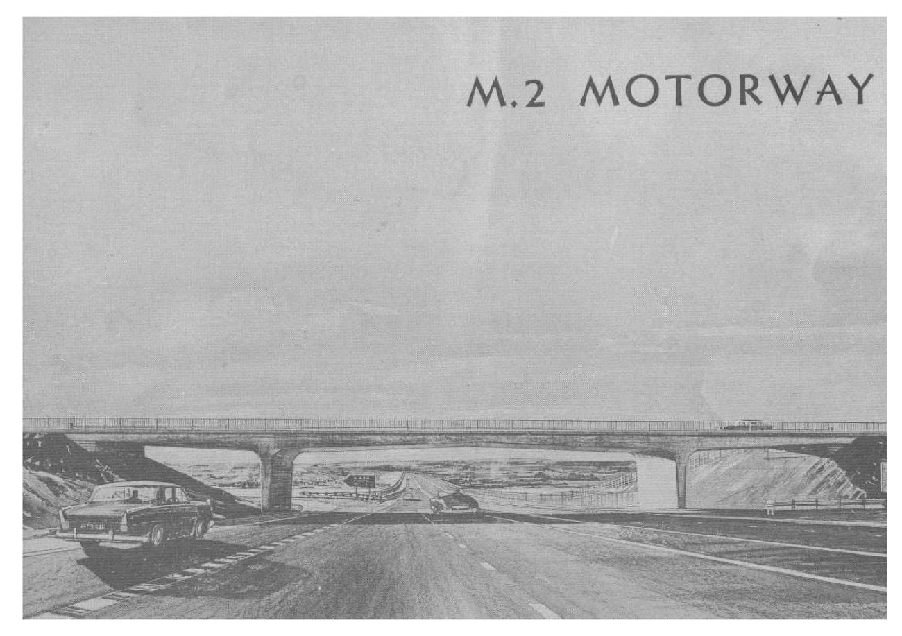
M2 Motorway opening booklet
Page 1
Page 2
Page 3
Page 4
Page 5
Page 6
Page 7
Page 8
Page 9
Page 10
Page 11
Page 12
Page 13
Page 14
Page 15
Page 16
Page 17
Page 18
Page 19
Page 20
Page 21
Page 22
Page 23
Page 24
Page 25
Page 26
Page 27
Page 28
Page 29
Page 30
Page 31
Page 32
M.2 MOTORWAY
MEDWAY TOWNS MOTOR ROAD
MINISTRY OF TRANSPORT
Consulting Engineers: FREEMAN, FOX AND PARTNERS
Associated with ROBERT F. EARLEY
Contractors:
- J. L. KIER & COMPANY LIMITED CHRISTIANI & NIELSEN LIMITED
- SYDNEY GREEN & SONS (CONTRACTORS) LIMITED
- GEORGE WIMPEY AND COMPANY LIMITED
- JOHN LAING CONSTRUCTION LIMITED
MEDWAY TOWNS MOTOR ROAD
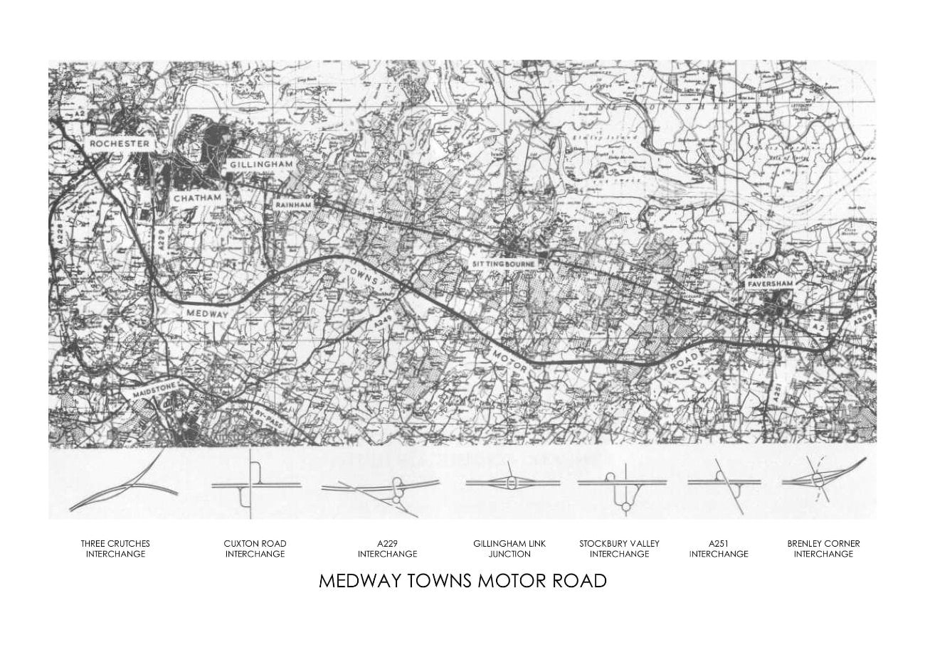
This 25 mile length of motorway leaves the existing A.2 road at "Three Crutches" approximately 2 miles west of Rochester Bridge and rejoins it nearly 2 miles east of Faversham of the junction of the A.2 and the A.299 (Thanet Way) giving easy access to this coastal road which serves the holiday resorts of north Kent.
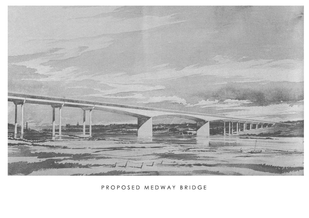
After leaving the A.2 at "Three Crutches", the motor road runs in a south-easterly direction to the River Medway. Immediately before the Medway Bridge is a two level interchange at the junction with the A.228; this is the first of five two level junctions with trunk roads along the motor road apart from the two terminal junctions.
The main spans of the Medway Bridge are of the cantilever type in prestressed concrete and the bridge, with its approaches, which are of pre-stressed pre-cast beams and in situ slab construction, is nearly two thirds of a mile long; although a motor road bridge it does incorporate facilities for carrying cyclists and pedestrians. These facilities are completely separate from the motor road and join with the existing road system at each end of the approach spans.
After leaving the Bridge the road continues in a south-easterly direction till its junction with A.229 where it turns and runs in a more easterly direction passing close to Bredhurst, Bredgar, Milstead and Newham before rejoining the A.2.
Owing to the hilly nature of the country the road will rise to a height of about 600-ft. above sea level between Bredhurst and the A.249. There are several deep valleys which necessitate the use of viaducts, the longest of which is at Stockbury Valley; this viaduct is over 850-ft. long and carries the road 70-ft. above ground level at the highest point.
Apart from the five junctions previously mentioned, all other roads as well as farm and pedestrian accesses will cross the motor road either under or over. This will mean the use of over 60 bridges.
Artists impressions of the various types of bridges have been approved by the Royal Fine
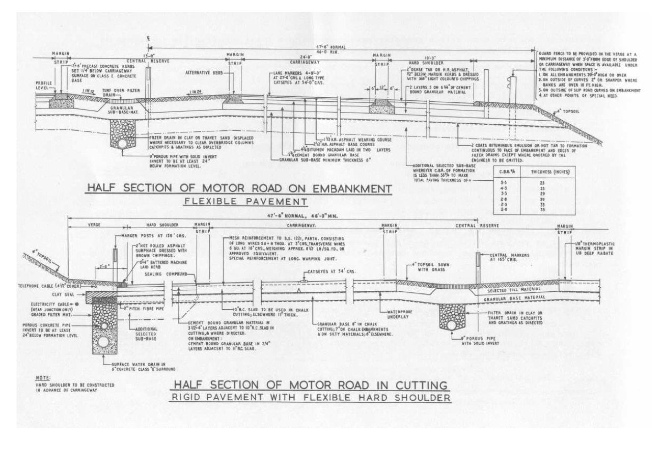
Art Commission. It was decided as a matter of policy that overbridges should be of similar appearance where possible. The road alignment both vertical and horizontal has been designed for a speed of 70 m.p.h., the minimum radius is 2,864-ft. and all curves under 11,460-ft. radius have transition spirals and are super-elevated.
The normal maximum gradient is 1 in 30.
Roadworks
The strata underlying the whole alignment of the motorway is chalk, which is exposed in the majority of deep cuttings. Elsewhere it is generally covered by varying thicknesses of "Clay with flints" or "Thanet sands". As the two last mentioned materials are very variable in quality, where possible the top two feet of embankments are being constructed with chalk. Furthermore, chalk is being used as a selected sub-base material 14" thick in cuttings through "clay with flints" where C.B.R's of the order of 2 may be expected.
The motorway is probably unique in having only two wet crossings throughout its whole
length, the River Medway and the Ospringe stream near Faversham which is only a brook. Drainage off the motorway has therefore been disposed of in soakaways excavated into the chalk which have been amplified in some instances by additional boreholes. Even in embankments the drainage is positively contained by a shallow kerb at the back of the hard shoulder and directed down precast concrete channels to ditches and the soakaways. In cutting the water is collected by gullies into a solid pipe while a porous concrete pipe takes any seepage from the sub-base and acts as a cut off drain. There is a porous pipe drain in the central median continuous through cutting and embankment.
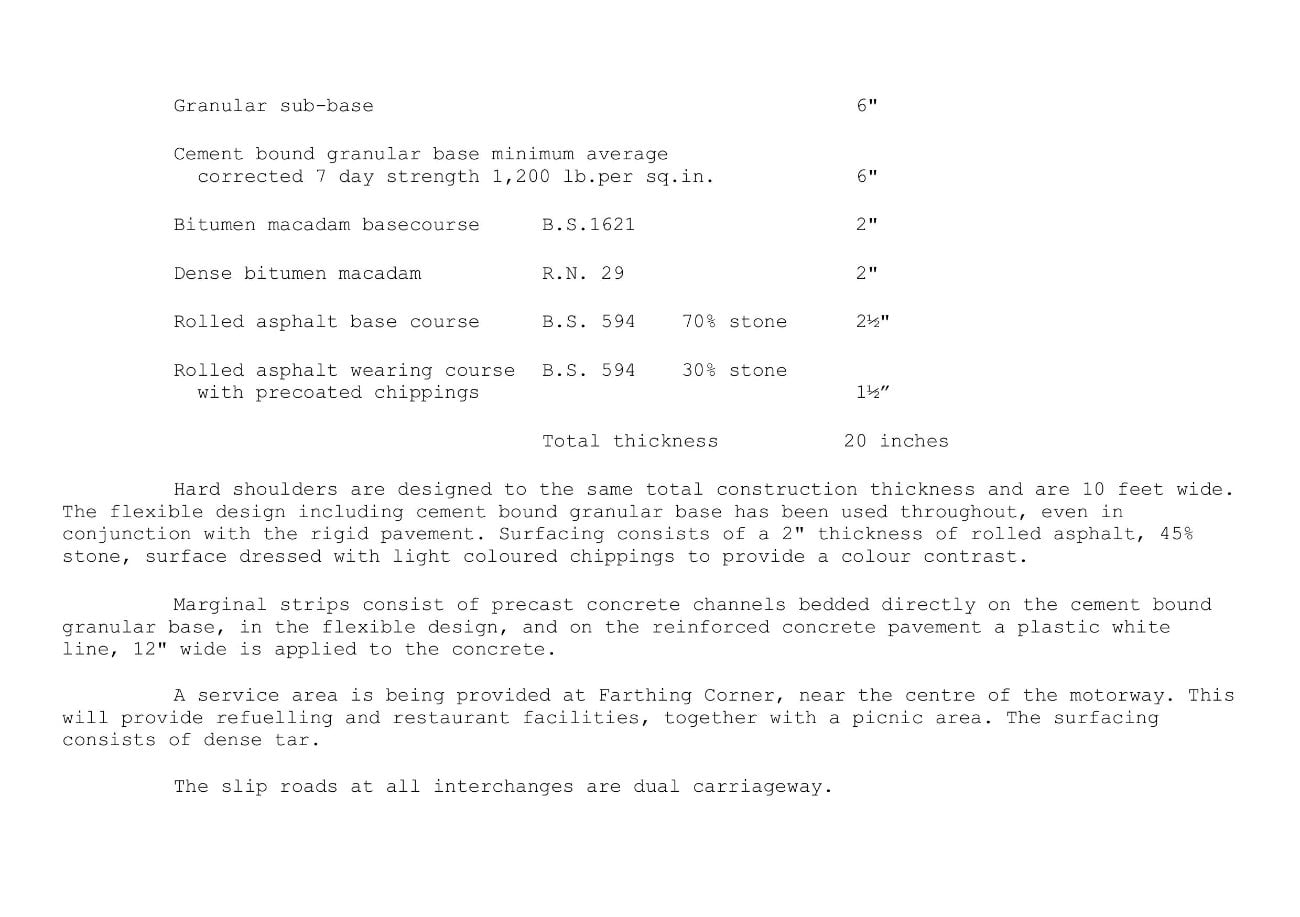
The construction thickness of the pavement has been arrived at largely to prevent frost heave of the chalk, the rigid pavement on Contract 4 calling for a 10" or 11" reinforced concrete slab with a granular base to make up a total construction thickness of 18". The flexible designs adopted on Contracts 2 and 3 consist of:
| Granular sub-base | 6" |
| Cement bound granular base minimum average corrected 7 day strength 1,200 lb.per sq.in. | 6" |
| Bitumen macadam basecourse B.S.1621 | 2" |
| Dense bitumen macadam R.N. 29 | 2" |
| Rolled asphalt base course B.S. 594, 70% stone | 24" |
| Rolled asphalt wearing course B.S. 594 with precoated chippings, 30% stone | 1½" |
| Total thickness | 20 inches |
Hard shoulders are designed to the same total construction thickness and are 10 feet wide. The flexible design including cement bound granular base has been used throughout, even in conjunction with the rigid pavement. Surfacing consists of a 2" thickness of rolled asphalt, 45% stone, surface dressed with light coloured chipping to provide a colour contrast.
Marginal strips consist of precast concrete channels bedded directly on the cement bound
granular base, in the flexible design, and on the reinforced concrete pavement a plastic white line, 12" wide is applied to the concrete.
A service area is being provided at Farthing Corner, near the centre of the motorway. This
will provide refuelling and restaurant facilities, together with a picnic area. The surfacing consists of dense tar.
The slip roads at all interchanges are dual carriageway.
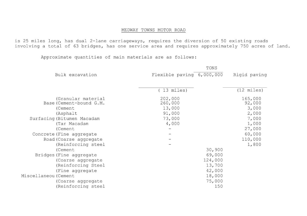
MEDWAY TOWNS MOTOR ROAD is 25 miles long, has dual 2-lane carriageways, requires the diversion of 50 existing roads involving a total of 63 bridges, has one service area and requires approximately 750 acres of land.
Approximate quantities of main materials are as follows:
| Flexible Paving (13 miles) | TONS | Rigid Paving (12 miles) | ||
|---|---|---|---|---|
| Bulk excavation | 6,000,000 | |||
| Base | Granular material | 202,000 | 165,000 | |
| Cement-bound G.M. | 260,000 | 92,000 | ||
| Cement | 13,000 | 3,000 | ||
| Asphalt | 91,000 | 2,000 | ||
| Surfacing | Bitumen Macadam | 73,000 | 7,000 | |
| Tar Macadam | 4,000 | 1,000 | ||
| Cement | - | 27,000 | ||
| Concrete Road | Fine aggregate | 60,000 | ||
| Coarse aggregate | 110,000 | |||
| Reinforcing steel | 1,800 | |||
| Bridges | Cement | 30,900 | ||
| Fine aggregate | 69,000 | |||
| Coarse aggregate | 124,000 | |||
| Reinforcing Steel | 13,700 | |||
| Miscellaneous | Fine aggregate | 42,000 | ||
| Cement | 18,000 | |||
| Coarse aggregate | 75,000 | |||
| Reinforcing steel | 150 | |||
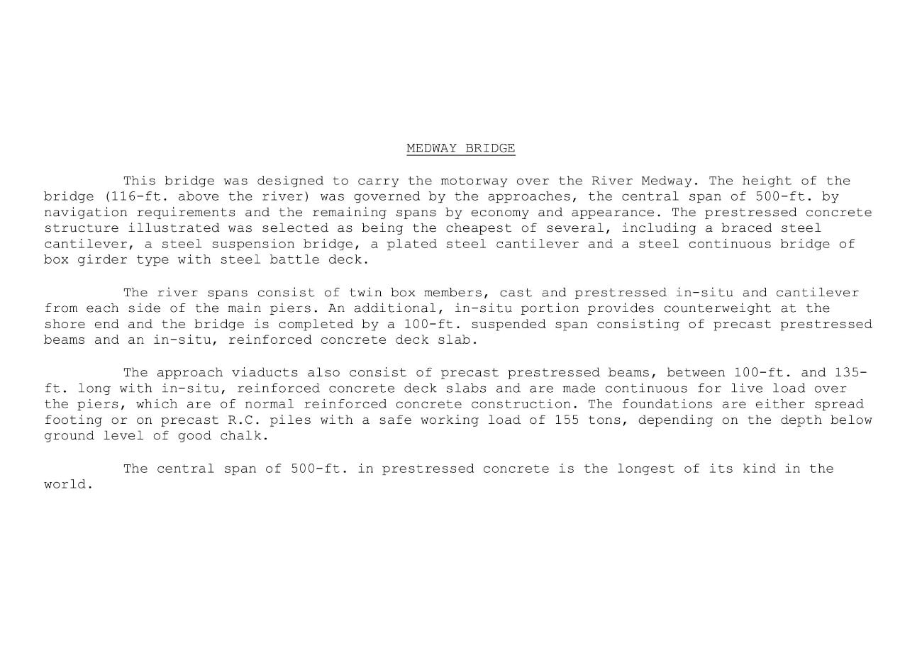
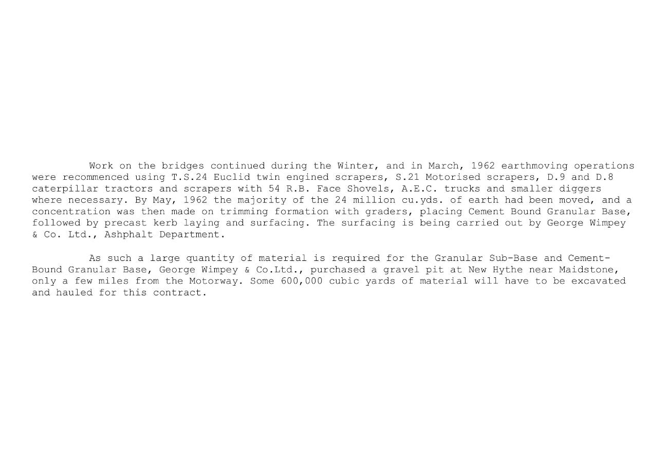
MEDWAY BRIDGE
This bridge was designed to carry the motorway over the River Medway. The height of the bridge (116-ft. above the river) was governed by the approaches, the central span of 500-ft. by navigation requirements and the remaining spans by economy and appearance. The prestressed concrete structure illustrated was selected as being the cheapest of several, including a braced steel cantilever, a steel suspension bridge, a plated steel cantilever and a steel continuous bridge of box girder type with steel battle deck.
The river spans consist of twin box members, cast and prestressed in-situ and cantilever from each side of the main piers. An additional, in-situ portion provides counterweight at the shore end and the bridge is completed by a 100-ft. suspended span consisting of precast prestressed beams and an in-situ, reinforced concrete deck slab.
The approach viaducts also consist of precast prestressed beams, between 100-ft. and 135-ft. long with in-situ, reinforced concrete deck slabs and are made continuous for live load over the piers, which are of normal reinforced concrete construction. The foundations are either spread footing or on precast R.C. piles with a safe working load of 155 tons, depending on the depth below ground level of good chalk.
The central span of 500-ft. in prestressed concrete is the longest of its kind in the
world.
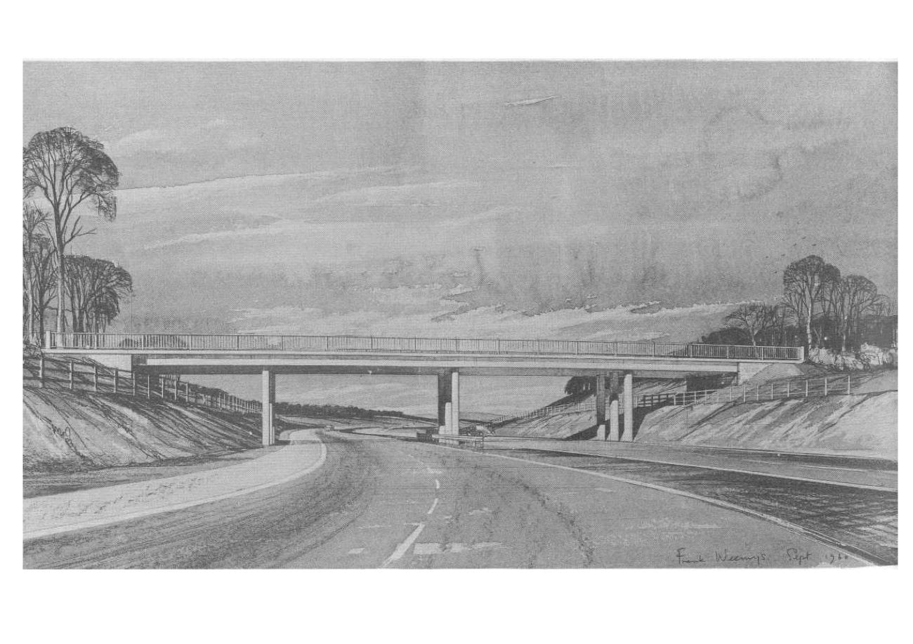
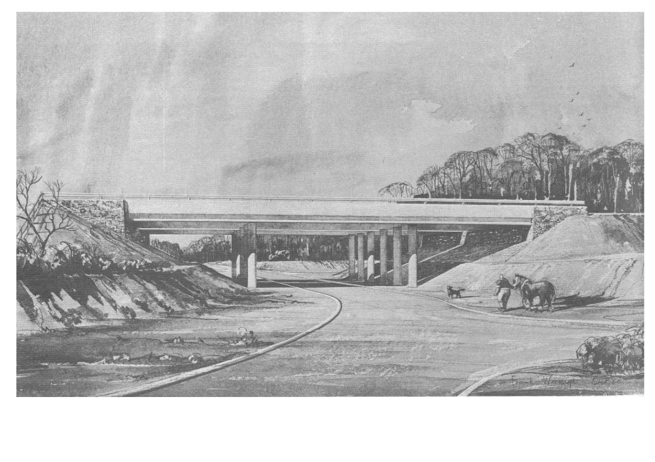
TYPICAL 4-SPAN OVERBRIDGES
These are provided to carry minor roads over the motorway.
The square span of the central spans is 45-ft. 9-ins.; most of these bridges are skewed
and some are curved.
These bridges are of reinforced concrete, the deck consisting of a slab generally 26-ins. thick, supported directly on integral columns with expansion bearings at the buried abutments.
Ducts for services are provided under the footways.
This type of bridge was chosen for its economy and for the ease and economy with which it can be adapted to moderate skews and curves. There are 14 bridges of this class and 8 variations of it.
TYPICAL 3-SPAN UNDERBRIDGE
These are provided to carry the motorway over minor roads in locations where adjacent junctions on the minor road require a line of sight through the side spans.
The centre span varies from 41-ft. 3-ins. to 52-ft. 0-ins.; the side spans are smaller and are governed by the sideslopes of the earthworks.
These bridges are of reinforced concrete, the deck consisting of a slab generally 23-ins. thick, supported directly on integral columns with expansion bearings at the buried abutments
There are 4 bridges of this class.
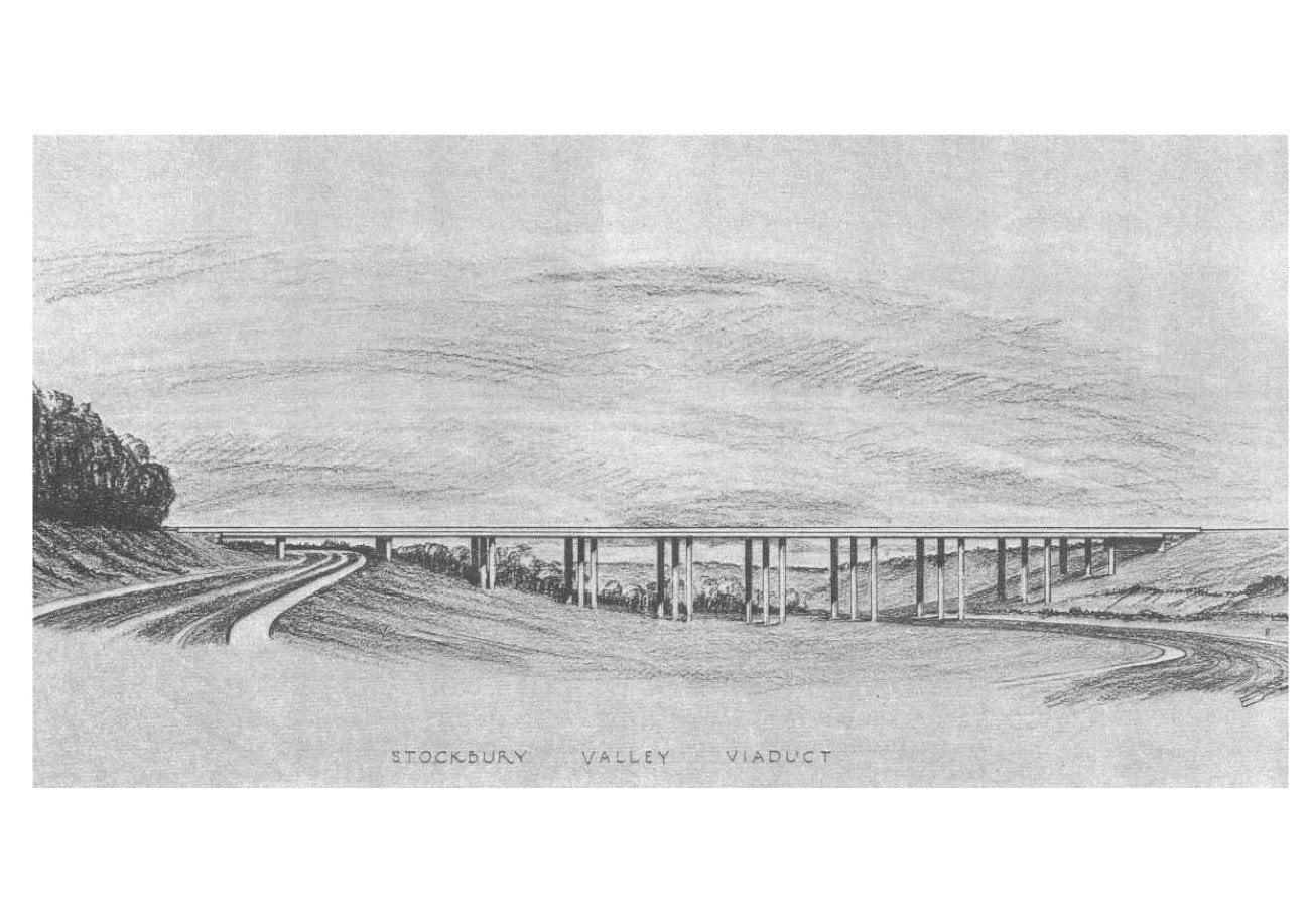
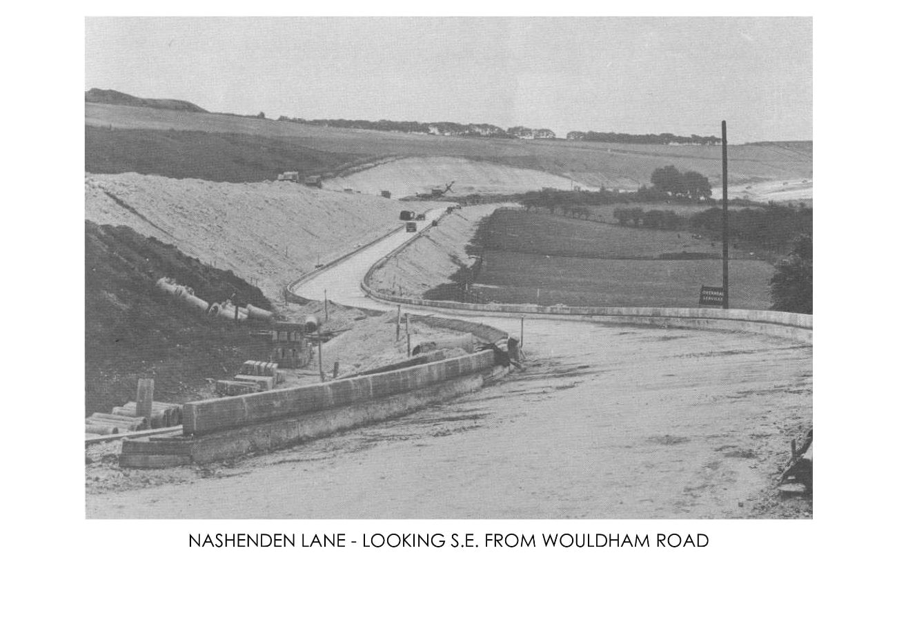
STOCKBURY VALLEY VIADUCT
This viaduct carries the motorway at a height of 70-ft. over the dry Stockbury Valley. The adjacent interchange with A.249 require the provision of accelerating lanes on the viaduct.
A number of alternative designs were considered, and the design adopted was chosen as being economical and at the same time having appearance in keeping with the other bridges on the motorway.
The spans, generally of 85-ft. were dictated by economics and by clearance requirements for the A.249 road and the west slip road.
The viaduct consists of in-situ prestressed concrete beam and slab construction, transversely reinforced, supported on two-bay portal piers the prestressed crossbeams of which are formed within the depth of the beams. The beams are simply supported in each span for dead load. Continuity for live load is provided by longitudinal reinforcement in the deck slab over the piers. The viaduct is founded generally on spread footings on chalk.
The piers are integral with the deck. A halved expansion joint is provided in the centre span, and fixed hinged bearings at the buried abutments.
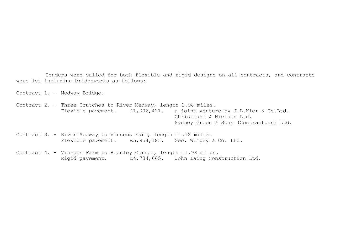
Tenders were called for both flexible and rigid designs on all contracts, and contracts were let including bridgeworks as follows:
Contract 1. - Medway Bridge.
Contract 2. - Three Crutches to River Medway, length 1.98 miles.
- Flexible pavement.
- £1, 006, 411.
- A joint venture by J.L.Kier & Co.Ltd., Christiani & Nielsen Ltd., Sydney Green & Sons (Contractors) Ltd.
Contract 3. - River Medway to Vinsons Farm, length 11.12 miles.
- Flexible pavement.
- £5,954,183.
- Geo. Wimpey & Co. Ltd.
Contract 4. - Vinsons Farm to Brenley Corner, length 11.98 miles.
- Rigid pavement.
- £4,734,665.
- John Laing Construction Ltd.
CONTRACT 1. - MEDWAY BRIDGE
Details of the methods used in the construction of the main bridge are given in the Cement and Concrete Association's booklet on the bridge and need not be repeated here.
Construction of the minor bridges adjacent to the abutments and the main bridge by the same organisation has reduced the adverse effects of limited working space in these areas and simplified programme phasing as well as resulting in some economies of plant and installations.
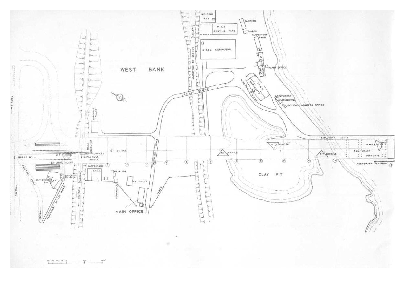
CONTRACT 2. - CONSTRUCTION
The bulk earth moving on this section amounts to ½ million cubic yards and has been carried out almost exclusively by tractor and scraper, on account of the relative short haulage involved. About half was completed during the first season. The initial section at Three Crutches is in Thanet Sand and it has been found necessary to stabilize with cement the top 12" layer of sand under the granular sub-base, where high equilibrium moisture contents may be expected in cutting. Stabilisation has been done in sit and normal agricultural equipment has been used to spread and mix the materials. The work has been done in two 6" layers with 3% cement in the lower layer and 5% in the upper. Compaction is by 3½ ton vibrating roller and 8 ton tandem smooth wheel roller with careful control of the moisture content. Thanet Sand has been used in forming the embankment at Fuel Pipe Bridge over a length of approximately 1000 ft. and with a maximum height of about 25 ft. this material has also been used in the approach embankments to Three Crutches bridge on the West bound A2. Compaction has been achieved by the use of 3½ ton vibrating rollers used in tandem.
In the shallow cutting in clay-with-flints which follows the sand embankment, a 14" layer of chalk has been placed as selected sub-base and has been compacted by a 12/15 ton smooth wheel towed roller. This material, from the deep chalk cutting adjacent to the Cuxton Road, has had moisture contents in the solid as high as 36% during the Winter months. It has not proved possible to work the material when the moisture content is above about 27%. The balance of chalk from the big chalk cutting has been used to form the high embankments across the Merrals Shaw Valley and at the Cuxton Road Interchange.
As-raised ballast materials for the granular sub-base are excavated in the Medway Valley.
The sub-base materials are spread by bulldozer and compacted by 16 ct vibrating tandem roller and 8 ton smooth wheel roller.
The cement-bound granular base in the carriageway and hard shoulders is placed by a Blaw Knox PF.90 paver and compacted by similar plant to the sub-base, 8% of cement being added in a 1% cubic yard batch mixing plant with weight batching arrangements located close to the Cuxton end of the Motorway. The mixed material transported to the paver in covered tipping wagons.
Placing of the black-top layers of bitumen macadam and hot rolled asphalt will be by conventional methods working from the Three Crutches end.
Construction of the four bridges crossing the motorway has been phased to suit the earth moving programme. Methods of construction have largely been conventional with extensive use of ready mix concrete. The columns for the bridge at Three Crutches are up to 28 ft. in height and although heavily reinforced are constructed in one lift. Birdcage scaffold of standard patent frames is used to support the deck soffit shutter of the two main bridges. The portal frame design carrying the Cuxton Road A228, is the only one of this kind on the Motorway and has a in situ prestressed deck slab with a centre span of 120 ft. and side spans of 48 ft. It is intended to place the 1400 cubic yards of concrete in the deck slab in one continuous operation.
The two remaining bridges on this contract are both underpasses, one being a farm access and the other for pedestrians only at Merrals Shaw. These have been constructed by conventional method, the only major problem being access under winter conditions.
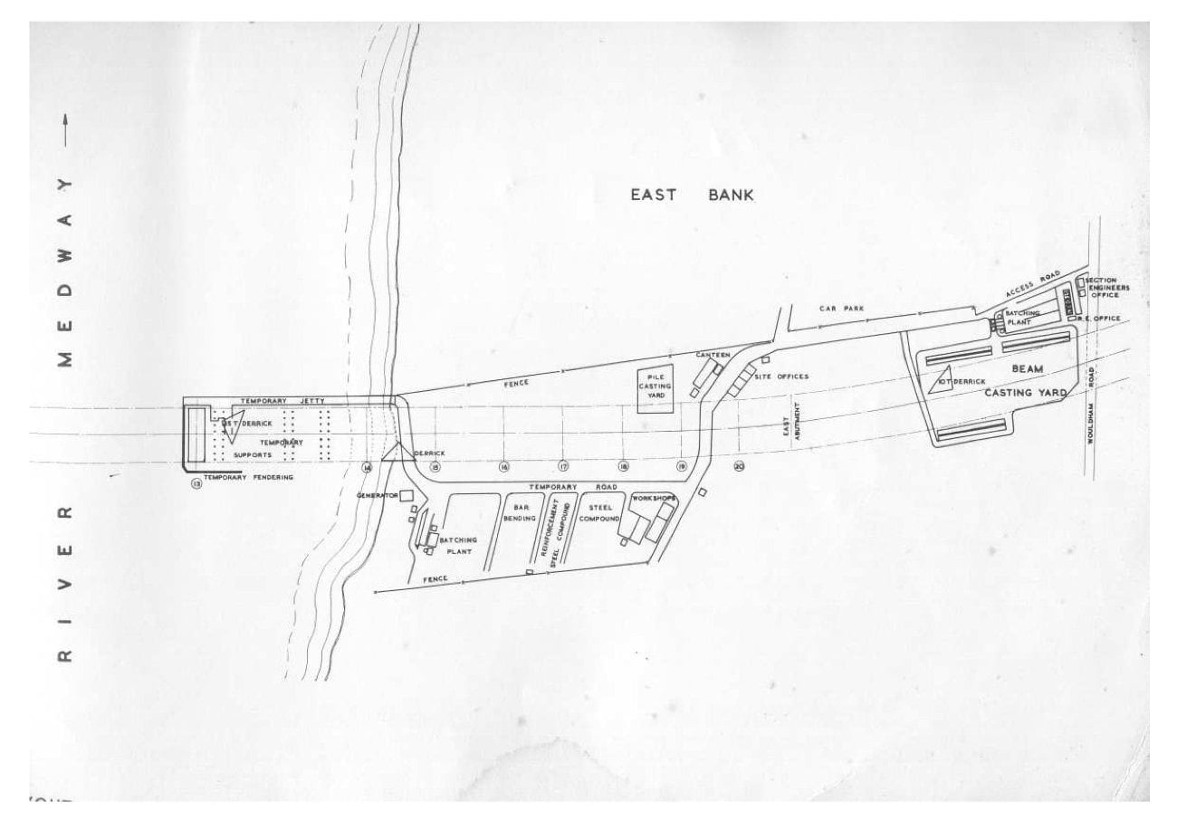
CONTRACT 3. - CONSTRUCTION
For the purpose of construction and control the contract was broken down into 4 main
sections these being:
- Motorway from the River Medway to Harp Farm.
- Motorway from Harp Farm to Oad Street.
- All road bridges, foot bridges, subways and large diameter culverts.
- Mixing and laying of Cement-Bound Granular Base.
Each section is controlled by an Agent directly responsible to the Project Manager, with supporting field services of Plant and Transport organizations.
Section I
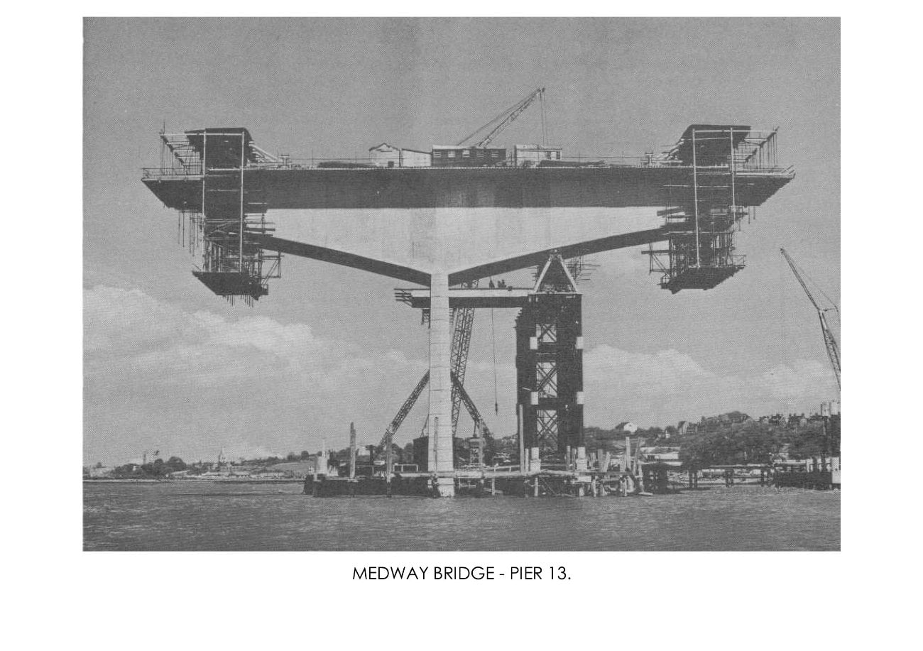
This section consists of some 5 miles of motorway and contains apart from the bridges a major interchange which connects the M.2. with the A.229 Rochester to Maidstone Road. The A.229 is carried over the motorway by a two-span overbridge, and the acute angle of 63° of the A.229 to the motorway at this point together with the nearness of the existing houses, some of them within 20 feet of the works, has caused considerable difficulties in the maintenance of traffic and services. The total excavation of soil, chalk and clay in this section consists of 1¼ million cu.yds of which ½ million cu.yds is to be used and compacted in road embankments, and the remainder, except for top soil, carted to spoil tips.
The majority of this section passes through extremely difficult country along the side of the Nashenden Valley where although stretches of the East bound carriageway are cut into the valley side to a depth of 40ft. the West bound carriageway is on some 20ft. of fill. Excavation commenced in July, 1961.
Section II
This section consists of some 6 miles of Motorway, and most meticulous planning of all earth moving was required because of the restriction of movement of heavy plant and transport caused by two natural barriers Mount Lane and Stockbury Valley. The total excavation of clay, chalk and sand including top soil is in the order of 12 million cu.yds. of which over 1 million cu.yds. will be placed and compacted in the embankment and the remainder carted to spoil tips.
The Service Area situated just South of Farthing Corner, and also Gillingham Link Junction
come within this section. Excavation commenced in August, 1961.
Bridges Section
The bridges to be constructed in this length of the Motorway are one six-span overbridge, nine four-span overbridges, two four-span overbridges, with prestressed beams, one three-span underbridge, four footbridges, four reinforced concrete subways, and three culverts which will carry services beneath the Motorway. In addition the contract includes two large viaducts and a further three-span underbridge which have been sub-contracted to the consortium of Kier-Christiani & Nielsen.
Mixing and Laying Cement Bound Granular Base
Three plants are used to mix the material, 2 Barber-Greene mixers and an A.P.100 Blaw Knox mixer. The laying is by Blaw Knox P.F.90. spreaders, and consolidation by vibrating and smooth wheeled rollers.
In this contract there is some 266,000 tons of Cement Bound Granular Base.
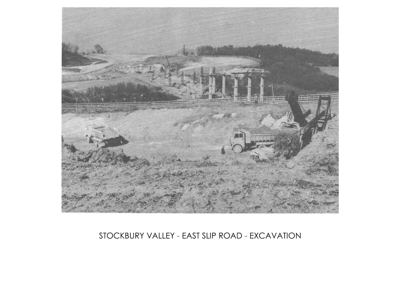
During the Summer of 1961, wooded areas were cleared which covered some 40% of the motorway, soil strip was carried out by D.9 and D.8 caterpillar tractors and scrapers, and earth moving by face shovels using A.E.C. trucks and tractors and scrapers. The fill was consolidated by vibrating and rubber tyred rollers, and by October, 1961 when it was necessary to close down on earthmoving operations because of bad weather some ¾ million cu. yds. had been moved.
Work on the bridges continued during the Winter, and in March, 1962 earthmoving operations were recommenced using T.S.24 Euclid twin engined scrapers, S.21 Motorised scrapers, D.9 and D.8 caterpillar tractors and scrapers with 54 R.B. Face Shovels, A.E.C. trucks and smaller diggers where necessary. By May, 1962 the majority of the 24 million cu.yds. of earth had been moved, and a concentration was then made on trimming formation with graders, placing Cement Bound Granular Base, followed by precast kerb laying and surfacing. The surfacing is being carried out by George Wimpey & Co. Ltd., Asphalt Department.
As such a large quantity of material is required for the Granular Sub-Base and Cement-Bound Granular Base, George Wimpey & Co.Ltd., purchased a gravel pit at New Hythe near Maidstone, only a few miles from the Motorway. Some 600,000 cubic yards of material will have to be excavated and hauled for this contract.
CONTRACT 4. - CONSTRUCTION
The motorway construction consists of rigid pavement with flexible hard shoulders. There are 28 structures which incorporate 20 overbridges and 8 underbridges, including Bottom Pond Viaduct spanning a valley, and Clock House Bridge, spanning the main London/Dover railway line below Faversham. The contract includes two major interchanges at the junctions with the motorway of the A251 and of the A2.
For administrative purposes Contract 4 is divided into two six-mile sections with headquarters at Faversham and section offices at Bredgar, near Sittingbourne, and also Faversham. The peak labour force engaged is about 1,000 men.
Earthmoving commenced in mid-August 1961. Various methods of compaction are used, depending on the nature of the excavated material, and in general four passes of a 3½ ton roller are followed by two passes of a 20-ton flat-wheeled roller, which achieves the specified compaction. The highest fill is approximately 55ft. and the deepest cut 30ft.
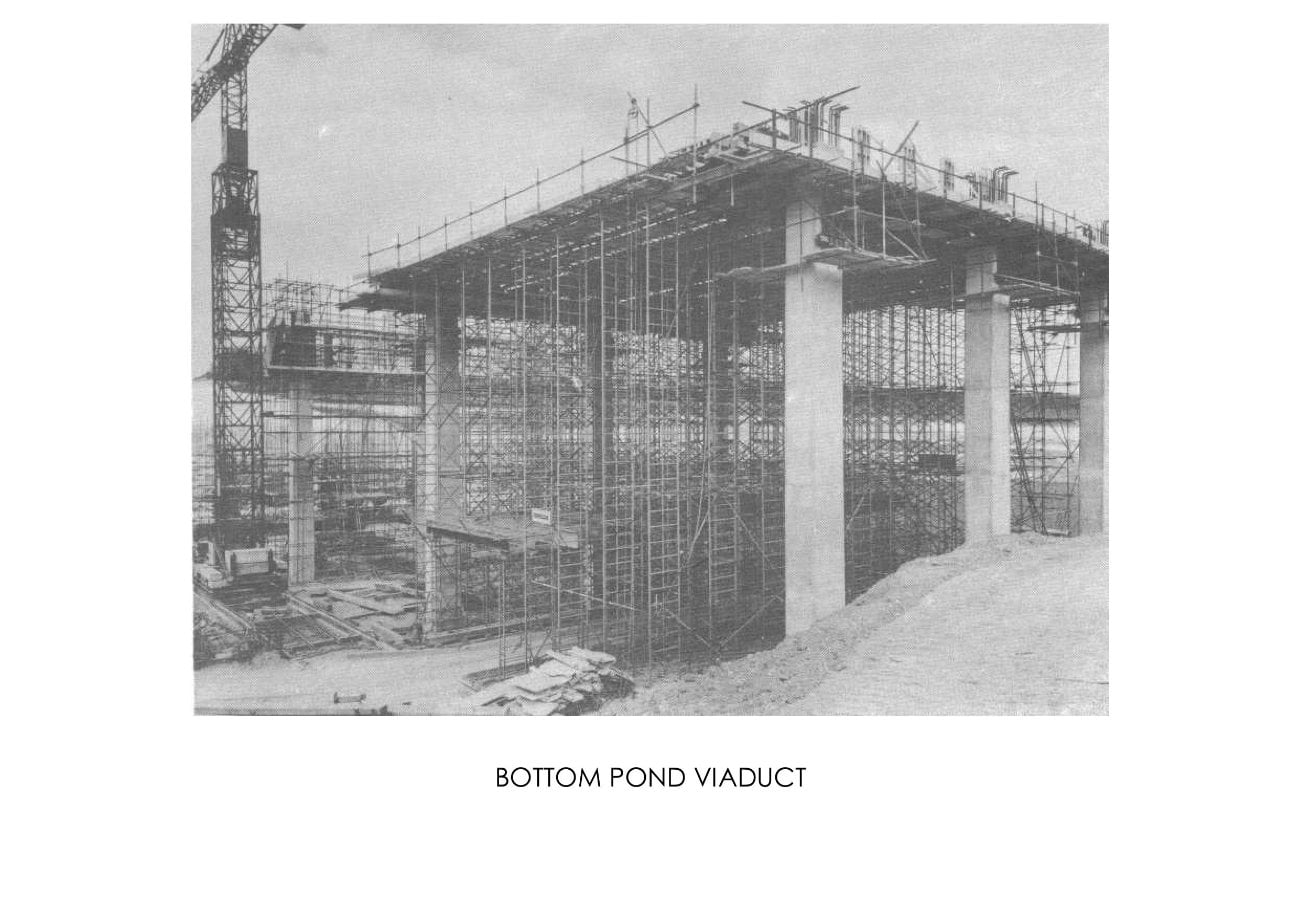
Bottom Pond Viaduct
The largest single structure on Contract 4 is the 375ft. long Bottom Pond Viaduct which spans a valley near the village of Milstead. This structure, which is being constructed by Holloway Brothers Limited as sub-contractors, has five 75ft. spans and the deck is so designed that it forms a continuous slab. The deck is supported on four piers, each consisting of three slender rectangular columns about 70ft. high. These are supported on groups of in situ reinforced concrete piles.
The construction of each span follows the same pattern: beams and slabs are cast while supported on scaffolding and after stressing the load is transferred to heavy rolled steel joists, braced together and supported temporarily for this purpose at the top of each bent of columns. When adjacent spans have been completed, the reinforced concrete cross-beam lying over each bent is cast and the continuity of the whole bridge deck is thus achieved.
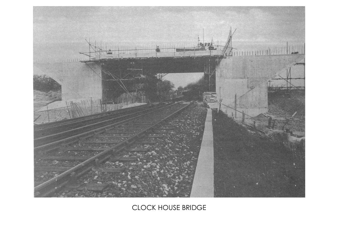
Clock House Bridge
This bridge carries the motorway over the main London/Dover railway and is a single-span underbridge with prestressed concrete deck. Each abutment is founded on 23 McKinney bored piles, 3ft. in diameter and approximately 32ft. long. Because railway traffic had to be maintained, it was necessary to sheet-pile the embankment along the face of the foundation beam to the west abutment, and a good deal of work had to be carried out at night during track possessions. To limit the number of possessions required it was decided to support the deck formwork on a travelling shutter supported by scaffolding. The 2 ft. thick deck slab, of 56ft. span, is simply supported and prestressed by the P.S.C. Freyssinnet multi-strand system and 88 cables are stressed to give a final force of 134 tons per cable.
Construction of Rigid Pavement
The pavement construction throughout Contract 4 consists of 11" or 10" of reinforced
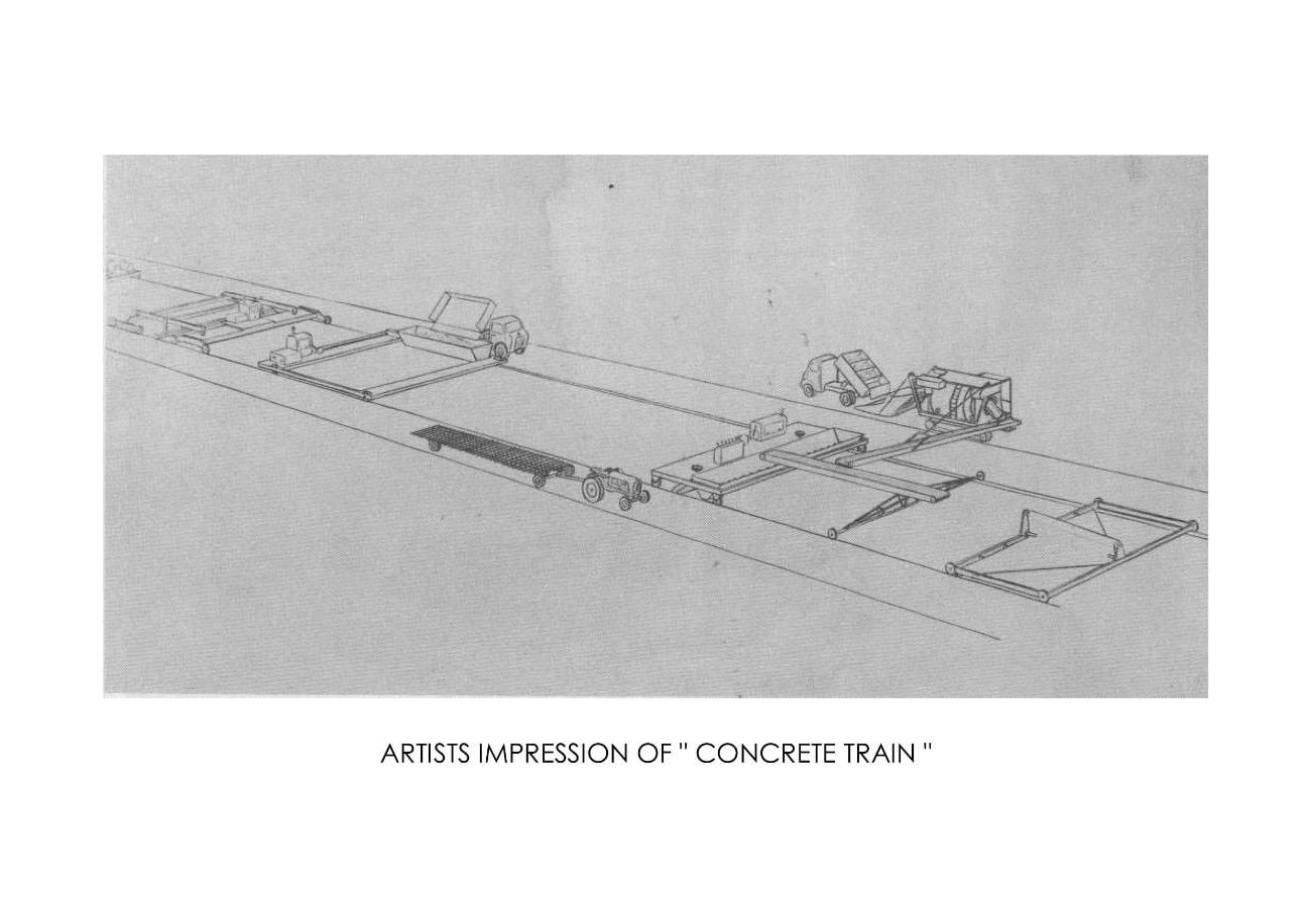
concrete slab, according to ground conditions. The slab is laid in two layers - the bottom layer being a relatively lean mix upon which mesh-reinforcement is laid. The top layer consists of 3" of high quality air-entrained concrete. The concrete train for laying the pavement in a continuous operation has been specially assembled and modified by John Laing Research and Development Limited, and the method is as follows:
- A layer of 150-gauge polythene is laid on the granular base by a specially designed dispenser.
- Dry-batched materials are delivered in four-compartment batching trucks to a Koehring Paver which discharges the mixed concrete for the bottom layer by means of two conveyor belts into a screw-spreader and compactor. This discharges the concrete finally across the 26ft. width and compacts it by means of a hydraulically-operated beam which imparts both pressure and vibration progressing at 4" steps of road at each compacting cycle.
- Mesh-reinforcement is then laid by hand in three widths of 8ft. 10.1/2" by 40ft. long;
- Air-entrained concrete of high workability is weigh-batched in side-tipping trucks, discharging into a hopper-spreader which spreads the concrete uniformly across the road slab;
- The final machine consists of a vibratory beam compacting unit in front, followed by a heavy finishing beam mounted in an articulated carriage. The effect of the articulator is to produce a very accurate finish.
- The finished concrete is protected before application of the curing membran by a length of waterproof tenting, which is towed behind the articulated finisher.
Concrete is batched at two central mixing plants - one to each six-mile section. Each plant consists of two independent units: A dry-batching plant for the bottom layer of the pavement and a wey batching plant for the top 3" layer.
M2 Medway Bridge opening booklet
Page 1

Page 2
Page 3

Page 4
Page 5
Page 6
Page 7
Page 8
Page 9
Page 10
Page 11
Page 12
Page 13
Page 14
Page 15
Page 16
Page 17
Page 18
Page 19
Page 20
Page 21
Page 22
Page 23
Page 24
Page 25
Page 26
Page 27
Page 28
Page 29
Page 30
Page 31
Page 32
Page 33
Page 34
Page 35
Page 36
THE MEDWAY BRIDGE ON THE M. 2 MOTORWAY
Consulting engineers and agents for the Ministry of Transport: FREEMAN, FOX AND PARTNERS
Contractors: J. L. KIER AND COMPANY, LIMITED; CHRISTIANI AND NIELSEN LIMITED
THE MEDWAY BRIDGE
INTRODUCTION
The Medway Bridge forms part of the new 25-mile long M.2 motorway, which will leave the existing A.2 main road one mile outside Strood and rejoin it 1½ miles beyond Faversham.
The motorway will eliminate traffic congestion in the Medway towns, which at present is choking the main route between London and Dover - especially during the summer months when holiday traffic streams towards the Channel ports and the north Kent coast.
The bridge crosses the River Medway between the City of Rochester and the Parish of Cuton. The exact position of the crossing was dictated by the line of the motorway which was tentatively fixed in 1954 by engineers from the Ministry of Transport and Civil Aviation, as it then was. Freeman, Fox and Partners were subsequently asked to report on the crossing, and several schemes in steel and concrete were investigated, the final choice being dictated by aesthetics as well as economics.
The report recommended that two bridge designs be prepared: one with the approach viaducts and main spans in prestressed concrete; the other with viaducts in prestressed concrete and the main spans in steel. Eventually, tenders were invited for a prestressed concrete bridge as well as two steel designs of similar appearance - one all welded, and the other welded and bolted. The designs were all approved by the Royal Fine Art Commission.
In August 1960, a tender for a prestressed concrete bridge submitted jointly by J. L. Kier and Company Limited and Christian and Nielsen Limited, was accepted at an estimated cost of about £2⅓ million, which was a few per cent cheaper than the welded and bolted steel alternative.
GENERAL DESCRIPTION OF THE BRIDGE
SPANS
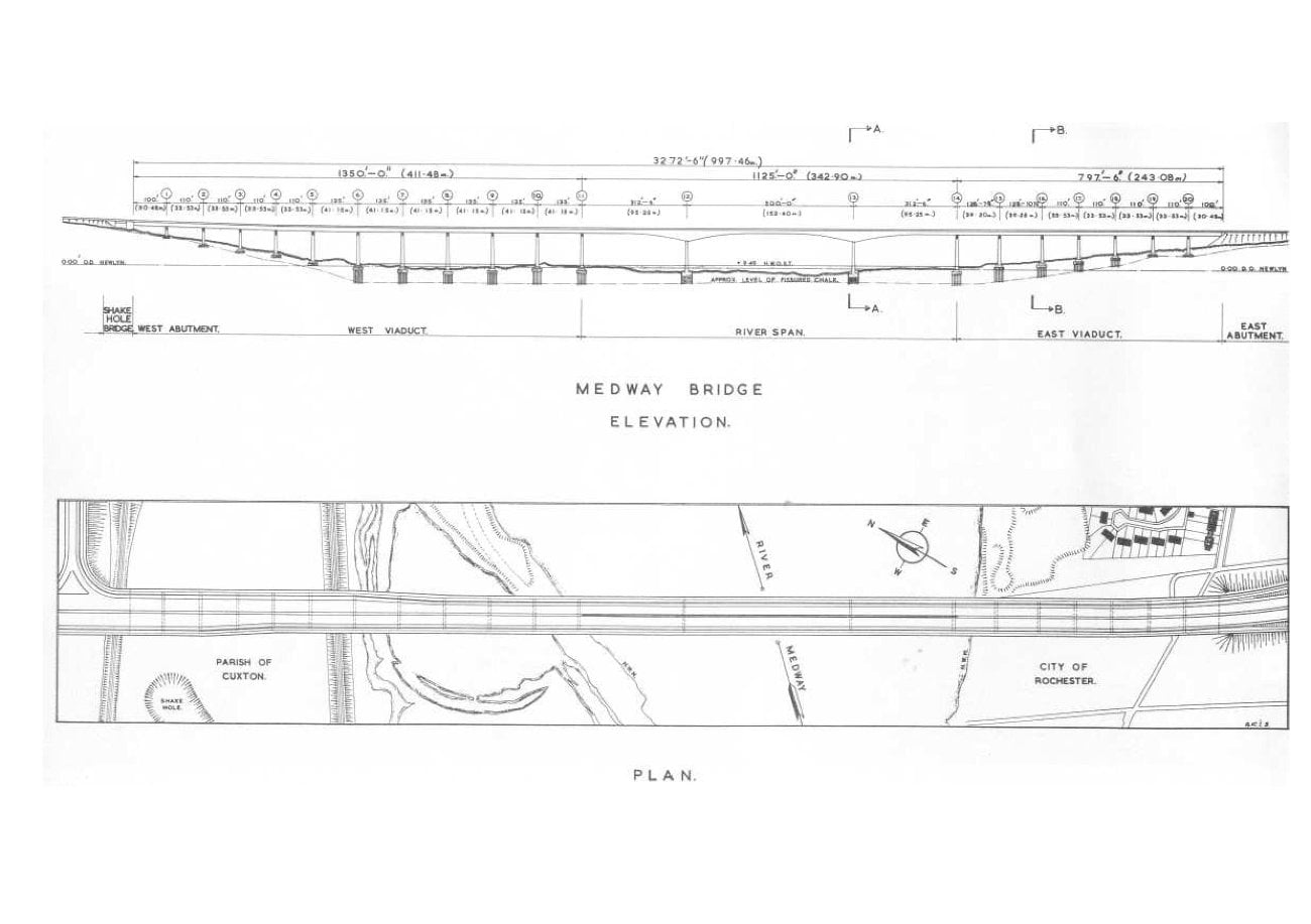
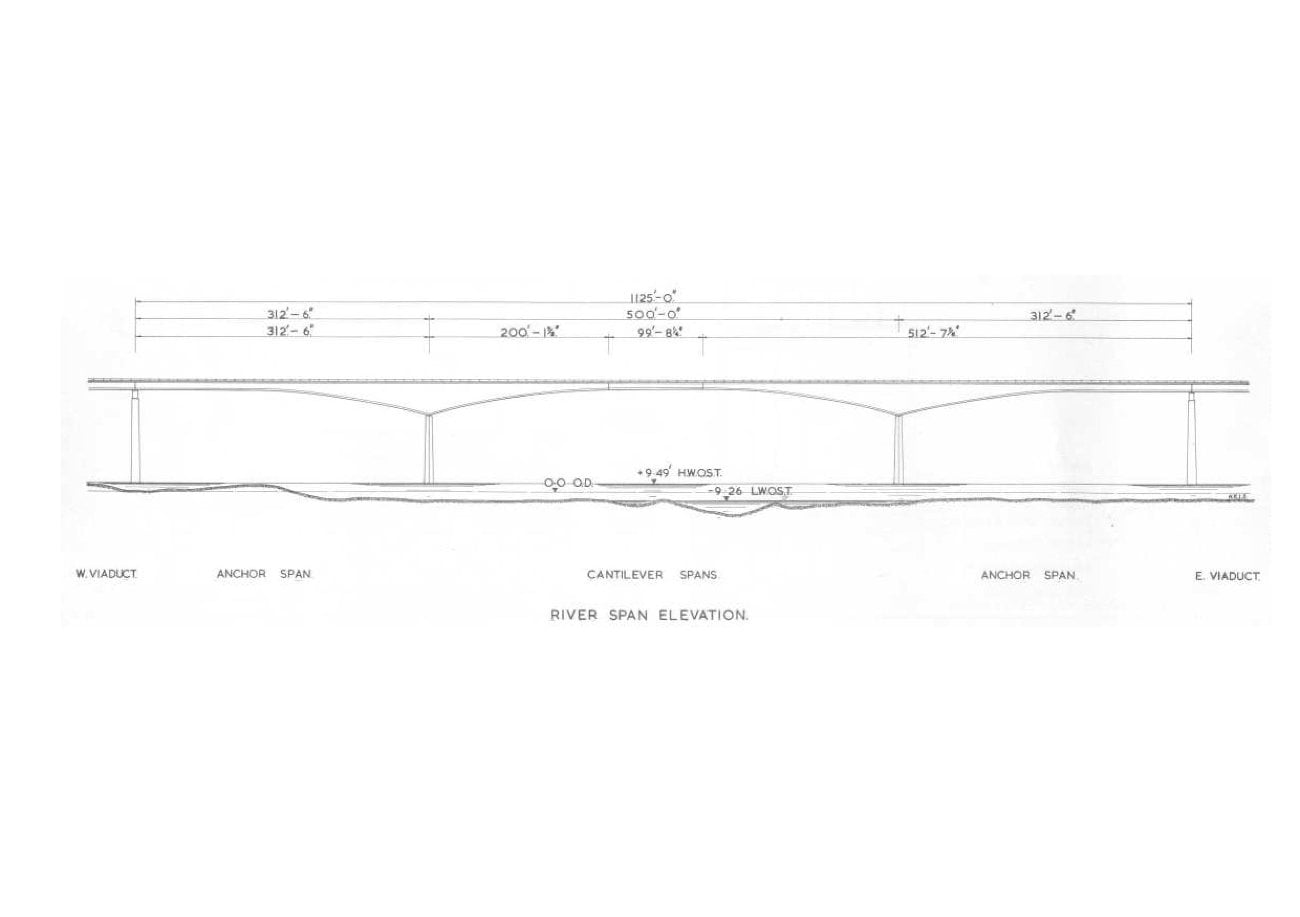
The bridge, with its approach viaducts, has an overall length of 3,272 ft 6 in. - nearly ⅔ mile. There are three spans over the river: a central span of 500 ft, to give the navigational clearance asked for by the Medway Conservancy Board, and two side spans of 312 ft 6 in., chosen for aesthetic and economic reasons.
The west viaduct has a total length of 1,350 ft and eleven spans; the east viaduct, a total length of 797 ft 6 in. and seven spans. The west abutment passes over the main railway line between London and the north Kent coast, and is known as Shake Hole Bridge. Another railway line, between Maidstone and Strood, passes below one of the spans of the west viaduct.
BRIDGE DECK
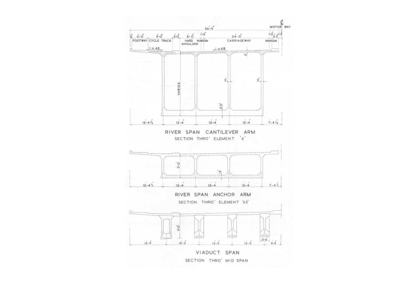
The bridge deck is, for the most part, 113 ft 6 in. wide. However, at the western end the width is increased to allow additional 12 ft lanes for acceleration and deceleration at the approach to the junction with the A.228 Cuton Road.
The bridge carries two 24 ft wide carriageways with 1 ft margin strips, flanked by 8 ft hard shoulders. Bicycle tracks and footpaths are also included, to cater for local requirements.
The carriageways are straight on plan, except for the last four spans of the east viaduct which lie partly on a 5° transition curve and partly on a circular curve of 2,865 ft radius. The west viaduct has a vertical curve between the abutment and piers 9 and 10, apart from which the bridge is horizontal throughout its length.
The top of the horizontal deck is 116 ft above Ordnance Datum Level. Although this is higher than necessary for navigational clearance over the river, it avoids excessive earthworks on the adjacent sections of the motorway.
The bridge carries G.P.O. services and has provision for future lighting of the carriageway if required. Navigation lights on the main piers and at the centre of the 500 ft span will be provided to guide shipping using the river.
THE BRIDGE STRUCTURE
ABUTMENTS
The west abutment is formed by Shake Hole Bridge, which itself has two abutments: the east one is of reinforced concrete cellular construction, whilst the west one is of mass concrete.
The cast abutment consists of a buried two-bay portal frame with tapered columns on spread footing foundations. The back of the abutment has vertical joints to minimize stresses arising from the bending of the bridge seat beam.
VIADUCTS
Foundations
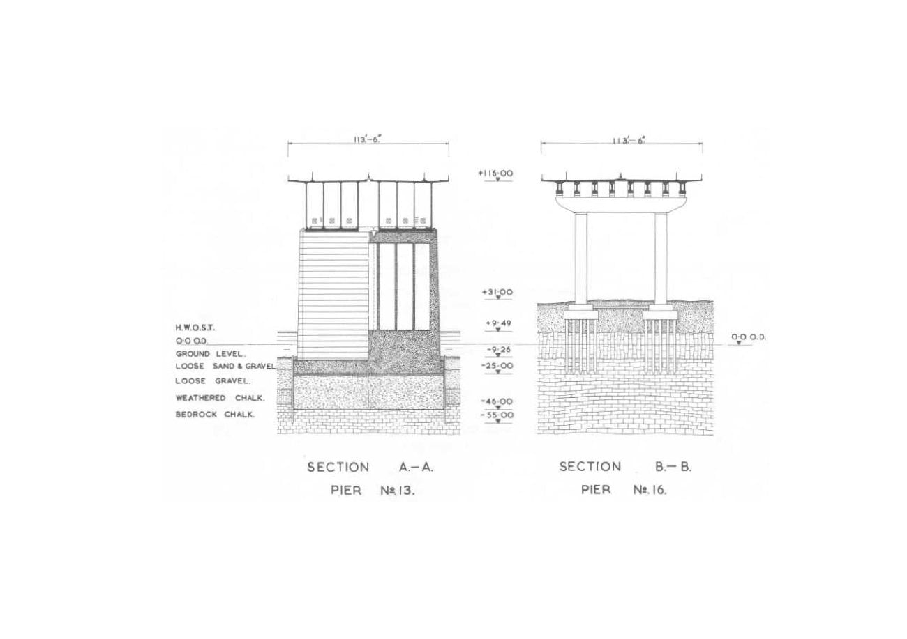
The viaduct piers rest on 22 in. hexagonal driven piles of solid reinforced concrete, except where the hard chalk stratum was less than about 20 ft below ground level, when spread reinforced concrete footings were used in preference. The piles vary in length from 40 ft to 65 ft.
Piers
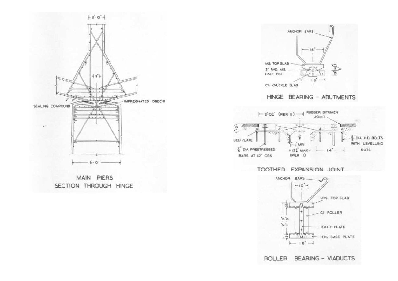
Each viaduct pier, with the exception of No. 1 at the extreme western end, consists of a reinforced concrete portal frame, cast in situ, varying in height from 30 ft to 100 ft above ground level. The columns are rectangular on plan with a taper, in their longitudinal direction, of 1 in 60. At their tops, they measure 7 ft 6 in. x 8 ft, or 7 ft 6 in. x 7 ft, according to their height. The cross beams are 10 ft 6 in. deep and either 6 ft 6 in. or 7 ft wide; they have cantilevered sections at each end to reduce the maximum moments. Pier No. 1 is solid, with a 2 ft thick wall between the columns to eliminate bending moments due to shrinkage in the portals.
Superstructure
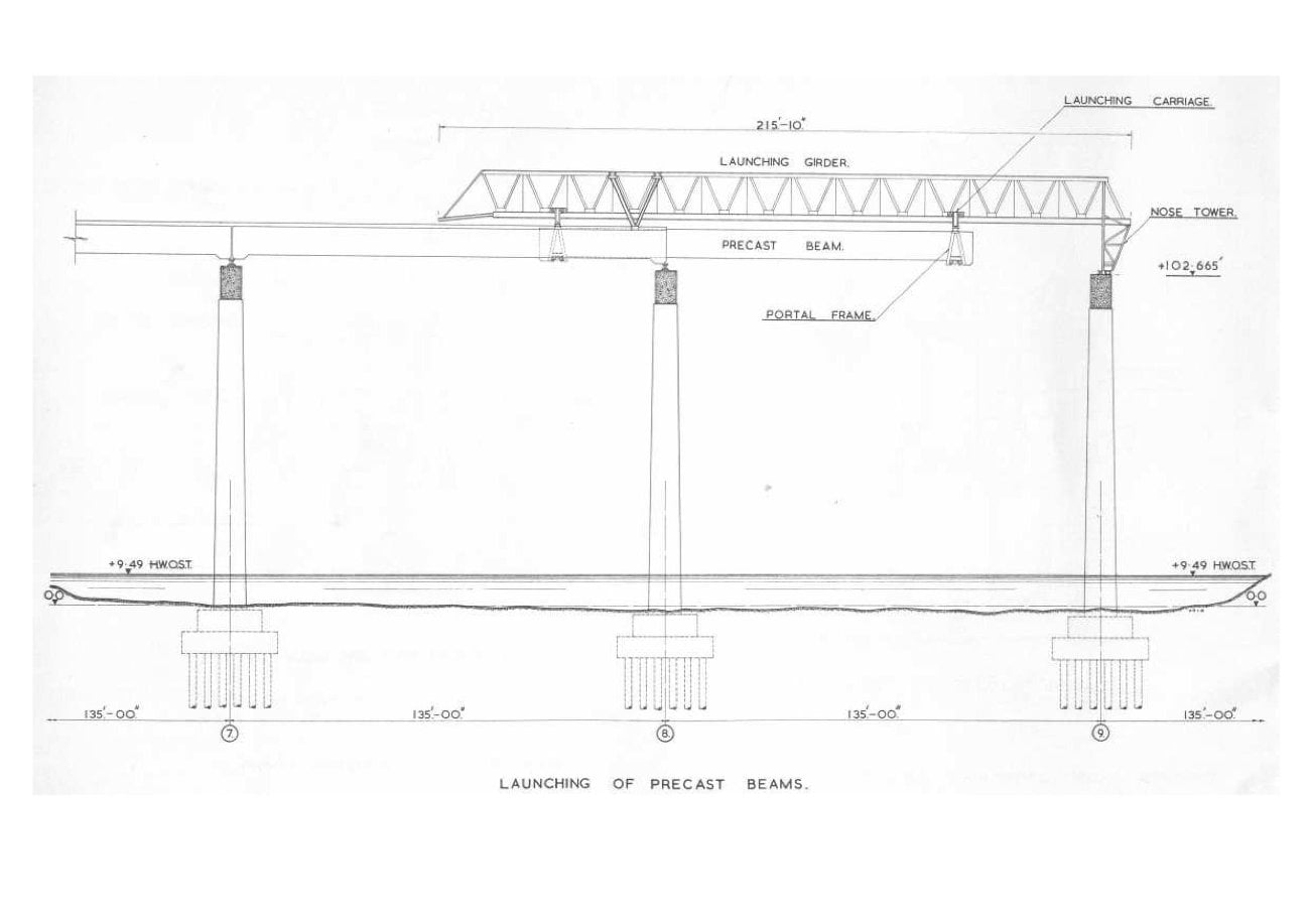
The viaduct superstructure is of composite beam and slab construction, simply supported for dead load and continuous for live load. For the most part, eight beams span between each pier, varying in length from 100 ft to 135 ft, with a maximum weight of about 190 tons. The beams are of precast concrete, prestressed with Lee McCall bars. The six inner beams are of I section, whilst the two outer ones are box beams to provide stiffness for the cantilevered section of the deck, and also to match the main spans over the river. The beams are generally placed at 12 ft 3 in. centres and support a 9 in. thick reinforced concrete deck slab, cast in situ. The slab is cantilevered out 10 ft 9 in. beyond the edge beams to carry part of the bicycle track and footway. The beams rest on roller bearings at each pier, the viaduct structures as a whole being anchored at the abutments which are designed to resist all longitudinal forces.
MAIN RIVER SPANS
Foundations
The foundations to the two main river piers are reinforced concrete spread footings, 31 ft wide and 106 ft long, founded at a depth of some 45 to 50 ft below mean water level.
Piers
The two main river piers consist of reinforced concrete shafts varying in thickness from 10 ft at the bottom to 6 ft at the top. The shafts are solid from the foundations to a height of 5 ft 6 in. above high water level; above this they are of cellular construction. The tops of the piers are heavily reinforced and incorporate continuous hinges cast in high quality concrete. The hinges resist all longitudinal forces, whilst providing free articulation for the two side spans.
Superstructure
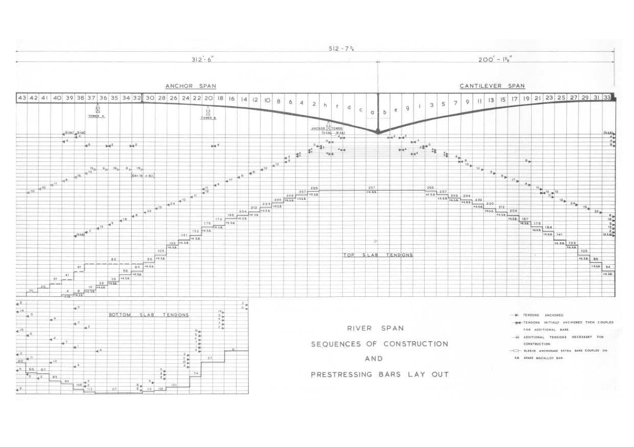
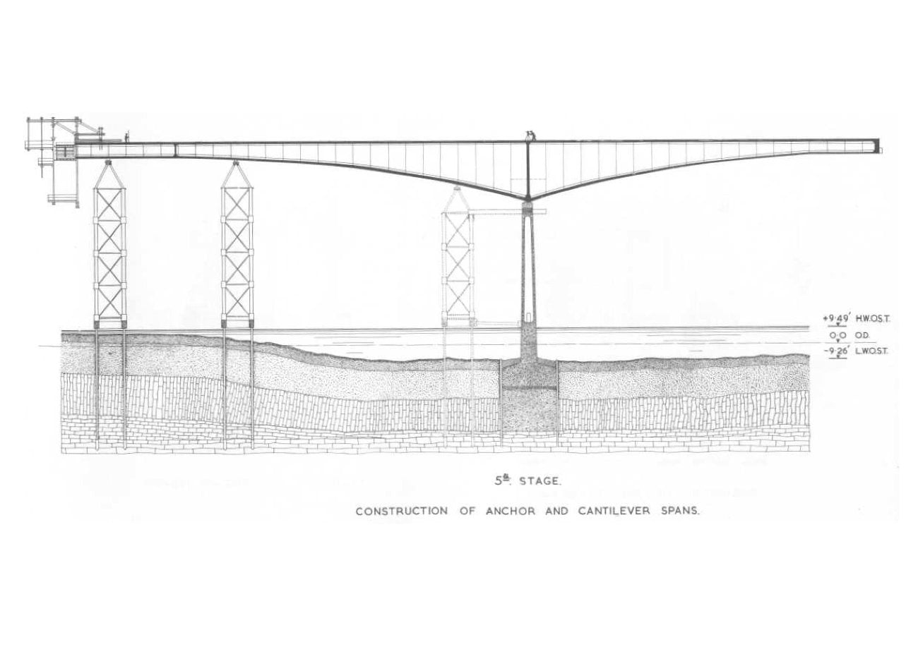
Each longitudinal half of the river-span superstructure, apart from a 100 ft gap in the centre, is carried by independent box girders of in situ concrete, cantilevered from the two main piers. Each girder consists of four 9 in. thick webs, a 9 in. thick top flange slab, and a bottom flange slab varying in thickness from 12 in. to 24 in. The top slab acts as the bridge deck and is cantilevered out 11 ft beyond the outer webs. The bottom slab is parabolic on the cantilever (central) arms and for part of the anchor (side) arms. The depth of the girders is 35 ft 6 in. over the main piers, 9 ft at the ends of the anchor arms, and 7 ft 4 in. at the ends of the cantilever arms. The girders are prestressed longitudinally and vertically by Lee McCall bars.
The 100 ft gap in the centre is bridged by a suspended span of similar construction to the viaduct superstructure. The two ends of the span, however, are half joints - one pinned and the other on rollers.
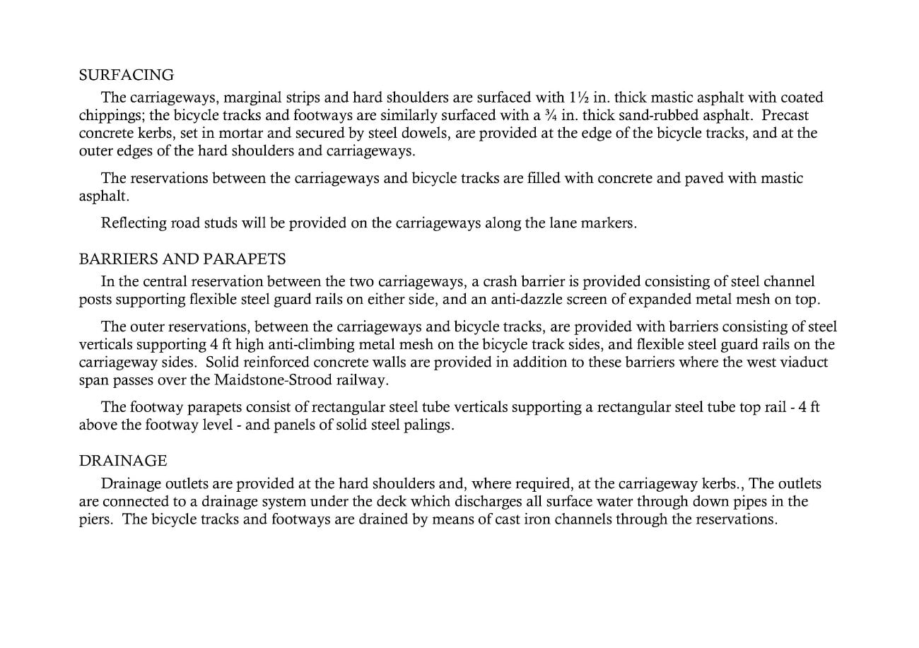
SURFACING
The carriageways, marginal strips and hard shoulders are surfaced with 1½ in. thick mastic asphalt with coated chippings; the bicycle tracks and footways are similarly surfaced with a ¾ in. thick sand-rubbed asphalt. Precast concrete kerbs, set in mortar and secured by steel dowels, are provided at the edge of the bicycle tracks, and at the outer edges of the hard shoulders and carriageways.
The reservations between the carriageways and bicycle tracks are filled with concrete and paved with mastic asphalt.
Reflecting road studs will be provided on the carriageways along the lane markers.
BARRIERS AND PARAPETS
In the central reservation between the two carriageways, a crash barrier is provided consisting of steel channel posts supporting flexible steel guard rails on either side, and an anti-dazzle screen of expanded metal mesh on top.
The outer reservations, between the carriageways and bicycle tracks, are provided with barriers consisting of steel verticals supporting 4 ft high anti-climbing metal mesh on the bicycle track sides, and flexible steel guard rails on the carriageway sides. Solid reinforced concrete walls are provided in addition to these barriers where the west viaduct span passes over the Maidstone-Strood railway.
The footway parapets consist of rectangular steel tube verticals supporting a rectangular steel tube top rail - 4 ft above the footway level - and panels of solid steel palings.
DRAINAGE
Drainage outlets are provided at the hard shoulders and, where required, at the carriageway kerbs., The outlets are connected to a drainage system under the deck which discharges all surface water through down pipes in the piers. The bicycle tracks and footways are drained by means of cast iron channels through the reservations.
INVESTIGATION AND DESIGN
SOIL SURVEYS
The soil surveys carried out in 1954 and 1958 showed that the River Medway runs in an old flat bottomed valley in the Middle and Upper Chalk, which has been partly filled in by deposits of gravel, sand and peat. The chalk is heavily fissured and varies in consistency, depending on the degree of softening round the fissures. At the top, it consists of pieces of hard chalk in a soft weathered matrix, but lower down it is more compact and there is little of the weathered matrix. It was decided to found all the piers on this material, either on piles or spread footings - depending on the depth of suitable chalk below ground or water level - the footings to be constructed in cofferdams where necessary.
FOUNDATIONS
For the viaduct pier foundations, piling was found to be practicable and tests were carried out on both bored and driven piles. In view of the difficulty in deciding when a bored pile had reached a chalk stratum capable of carrying the loads, driven shells piles were specified with a safe working load of 155 tons. However, the contractor finally chose the solid hexagonal piles which have been used. Loading tests have shown that these piles give a permanent settlement of about 1/ 10 in. under 1½ times the working load.
With piers 1 to 5, at the end of the west viaduct, where spread footings have been used, excavations revealed a pronounced fissuring of the chalk formation, the main fissures running parallel with the river. It was therefore thought prudent to grout the formation by drilling for about 20 ft and by pressure-grouting below the footings, to provide lateral stability to the blocks of chalk.
In order to avoid any underwater obstacles to shipping, the foundations to the two main river piers had to be below the river bed level, and it was found that spread footings of the dimensions used would be the most economical.
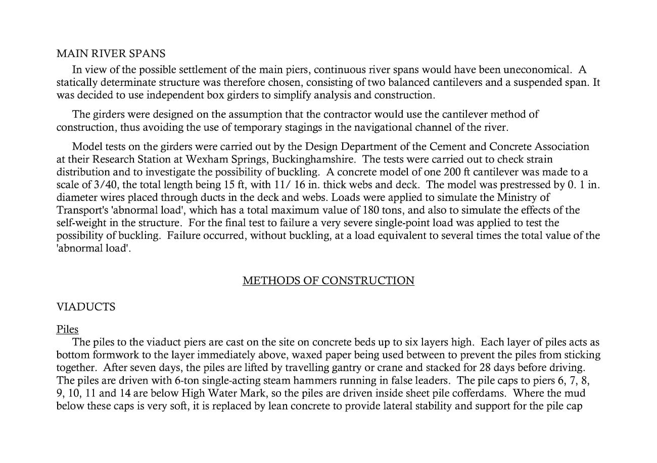
MAIN RIVER SPANS
In view of the possible settlement of the main piers, continuous river spans would have been uneconomical. A statically determinate structure was therefore chosen, consisting of two balanced cantilevers and a suspended span. It was decided to use independent box girders to simplify analysis and construction.
The girders were designed on the assumption that the contractor would use the cantilever method of construction, thus avoiding the use of temporary stagings in the navigational channel of the river.
Model tests on the girders were carried out by the Design Department of the Cement and Concrete Association at their Research Station at Wexham Springs, Buckinghamshire. The tests were carried out to check strain distribution and to investigate the possibility of buckling. A concrete model of one 200 ft cantilever was made to a scale of 3/40, the total length being 15 ft, with 11/16 in. thick webs and deck. The model was prestressed by 0. 1 in. diameter wires placed through ducts in the deck and webs. Loads were applied to simulate the Ministry of Transport's 'abnormal load', which has a total maximum value of 180 tons, and also to simulate the effects of the self-weight in the structure. For the final test to failure a very severe single-point load was applied to test the possibility of buckling. Failure occurred, without buckling, at a load equivalent to several times the total value of the 'abnormal load'.
METHODS OF CONSTRUCTION
VIADUCTS
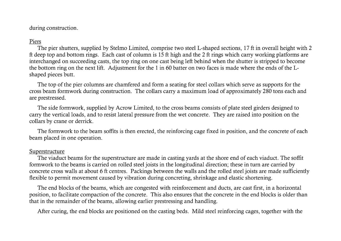
Piles
The piles to the viaduct piers are cast on the site on concrete beds up to six lavers high. Each layer of piles acts as bottom formwork to the layer immediately above, waxed paper being used between to prevent the piles from sticking together. After seven days, the piles are lifted by travelling gantry or crane and stacked for 28 days before driving.
The piles are driven with 6-ton single-acting steam hammers running in false leaders. The pile caps to piers 6, 7, 8, 9, 10, 11 and 14 are below High Water Mark, so the piles are driven inside sheet pile cofferdams. Where the mud below these caps is very soft, it is replaced by lean concrete to provide lateral stability and support for the pile cap during construction.
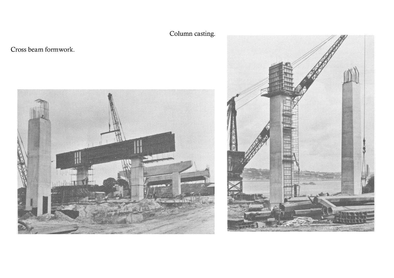
Piers
The pier shutters, supplied by Stelmo Limited, comprise two steel L-shaped sections, 17 ft in overall height with 2 ft deep top and bottom rings. Each cast of column is 15 ft high and the 2 ft rings which carry working platforms are interchanged on succeeding casts, the top ring on one cast being left behind when the shutter is stripped to become the bottom ring on the next lift. Adjustment for the 1 in 60 batter on two faces is made where the ends of the L-shaped pieces butt.
The top of the pier columns are chamfered and form a seating for steel collars which serve as supports for the cross beam formwork during construction. The collars carry a maximum load of approximately 280 tons each and are prestressed.
The side formwork, supplied by Acrow Limited, to the cross beams consists of plate steel girders designed to carry the vertical loads, and to resist lateral pressure from the wet concrete. They are raised into position on the collars by crane or derrick
The formwork to the beam soffits is then erected, the reinforcing cage fixed in position, and the concrete of each beam placed in one operation.
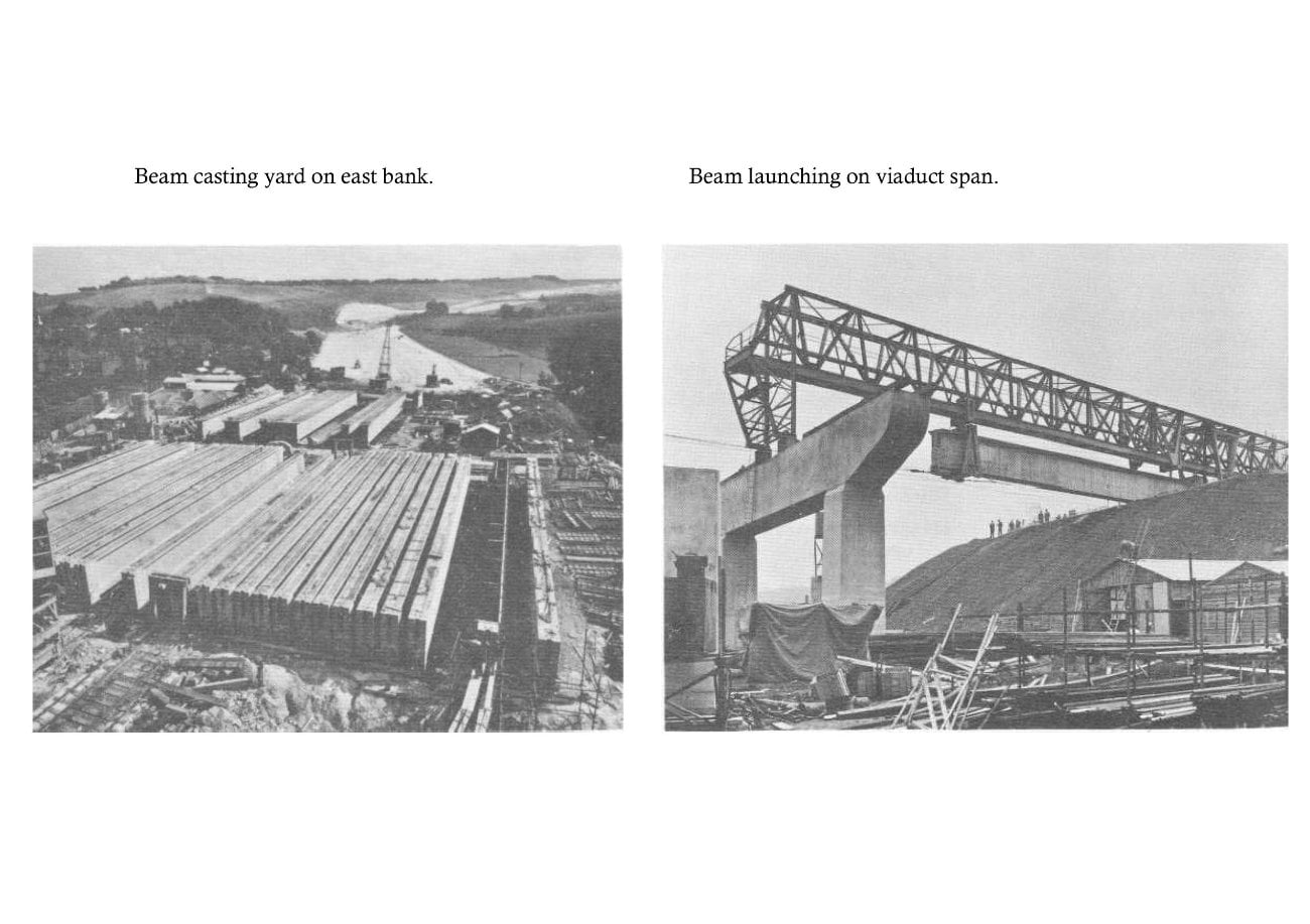
Superstructure
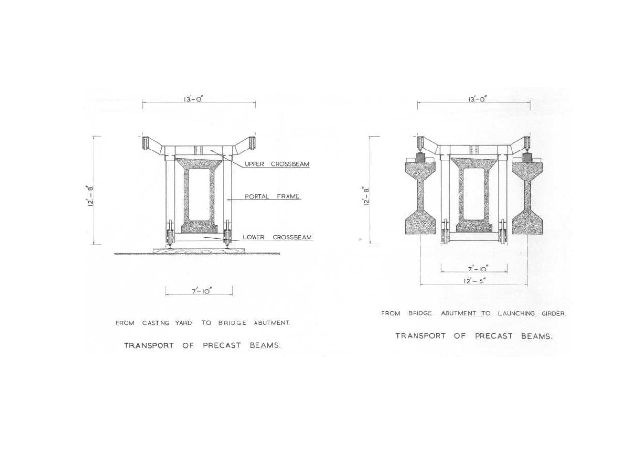
The viaduct beams for the superstructure are made in casting yards at the shore end of each viaduct. The soffit formwork to the beams is carried on rolled steel joists in the longitudinal direction; these in turn are carried by concrete cross walls at about 6 ft centres. Packings between the walls and the rolled steel joists are made sufficiently flexible to permit movement caused by vibration during concreting, shrinkage and elastic shortening.
The end blocks of the beams, which are congested with reinforcement and ducts, are cast first, in a horizontal position, to facilitate compaction of the concrete. This also ensures that the concrete in the end blocks is older than that in the remainder of the beams, allowing earlier prestressing and handling.
After curing, the end blocks are positioned on the casting beds. Mild steel reinforcing cages, together with the prestressing ducts and tendons are then fixed in place, the latter supported on preformed steel locating frames. The formwork is of steel with brackets welded on at intervals to hold the external vibrators. The concrete is placed by bottom-opening skips, lifted by a derrick which also handles all other materials and formwork in the yard.
The remainder of the I beams are cast in one operation, the box beams in two. The U sections of the box beams are cast first and subsequently the top slabs, the soffit formwork to these being left inside the beams. After striking the side forms, two bars are stressed to counteract shrinkage. After three days, sufficient bars are stressed for the beams to be jacked, rolled sideways on steel balls, and stored. Final stressing is carried out after 28 days, and all the ducts subsequently grouted. Gamma ray tests are made to check the efficiency of the duct grouting.
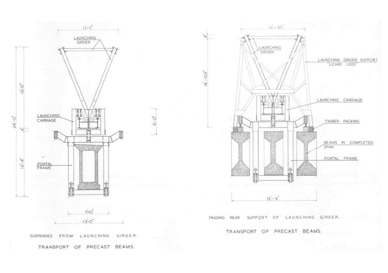
The completed beams are picked up from the storage yard and carried to within reach of the launching equipment by portal carriages which run on tracks, placed initially on the approach ramps to the abutments, and subsequently on two beams of a completed span.
The launching equipment consists of a steel trussed girder, triangular in section, with a front tower support and rear leg supports. The girder is travelled forward on a bogie under the leg supports, with the tail end of the girder counter-balanced by the first box beam for the next span to be launched, and the main part of the girder cantilevered forward from the legs. The launching bogie runs on the top of beams already placed in the previous span. When the forward tower has reached the pier ahead the nose is jacked down, the bogie removed and the rear legs packed. The concrete beams are transported across the span on two carriages running on the bottom chord of the girder, then jacked down and rolled sideways into position on steel balls.
When beams on adjacent spans have been placed in position, short stressing bars connecting brackets below the bottoms of the beams are stressed, and the beams are jacked down onto permanent bearings. The in situ deck slab is now cast, with the exception of short sections over the piers which are left un-cast to preserve the simply-supported state of the beams. The final stage is the casting of diaphragms between the beam ends together with the remaining portion of deck slab.
MAIN RIVER SPANS
Foundations
Excavations for the river pier foundations have been carried out inside steel sheet pile cofferdams, and for most of the work, grabs of various types have been used. In the final stages of excavation, the material immediately above formation level and that clinging to the sheet piles was loosened by water jets guided by divers. Final preparation of the formation was completed by divers operating an air lift, which brought up the slurry and loose chalk. Large lumps of chalk had to be manhandled into the grab.
The fissuring of the chalk made de-watering impossible. The cofferdams were therefore sealed by 21 ft thick plugs of concrete placed under water by special bottom-opening skips of 4 cu. yd capacity. For bottoming and plugging, the pier foundations were divided into five sections each by placing precast concrete panels vertically across the cofferdams and holding them in position by 'Universal' steel beams. After de-watering the cofferdams, the top of the underwater concrete was cleaned and levelled off; the reinforced concrete slab was then cast on top in the dry.
Piers
The main river piers are cast in 9 ft lifts using timber formwork with horizontal grooves at 4 ft centres to mask construction joints and shutter bolt holes.
Superstructure
The main river-span superstructure is constructed in two longitudinal halves, the system of construction being identical in both cases.
The girder sections over the piers are constructed first and are partly of precast concrete units supported on steel beams spanning between the main piers and temporary steel towers located in each shore span.
Each girder is then built out in 10 ft sections on either side of a pier, care being taken to keep a downward reaction on the steel tower to guard against overbalancing. Vertical timber boarding is used for the outside of the girders; plywood panels are mainly used for the inside. Formwork for each stage is supported from a cantilevered carriage on either side of a pier, anchored to the previously completed sections. Each section is cast, allowed to harden and then stressed by Lee McCall bars. Stresses in the girders are checked at every stage of construction to ensure that they are within permissible limits during erection as well as under working conditions.
As the cantilevered construction proceeds and the two carriages get further away from the pier, the out of balance moments grow larger and the reactions on the steel tower become excessive. A second tower is therefore erected, approximately 160 ft from the end of the anchor span. As soon as this tower is passed by the cantilevered carriage in this span, the support to the concrete girder is transferred from the first to the second tower. The cantilever arm is completed first, being only 200 ft long as compared to the 312 ft long anchor arm. The cantilevered carriage for this section is then dismantled and used again for the construction of the anchor arm of the second half of the bridge.
The cantilevered construction of the anchor arm is continued as far as the negative moment over the tower, in relation to the cross section of the bridge, will allow. A third tower is then erected, and a controlled reaction introduced by means of hydraulic jacks.
The construction of the anchor arm is next completed, the reaction over the third tower being carefully controlled so that the bending moment on the second tower should not be in any way increased.
When the structure is complete, there are only positive bending moments in the last 75 ft of the anchor arms; prestressing tendons are therefore placed in the bottom slabs. It is necessary, for construction purposes, to introduce some extra top tendons in these sections of the anchor arms. These extra tendons are finally removed, the girders being then simply supported by hinges at the main piers, and rollers at the shore piers.
The 100 ft suspended span over the centre of the river is cast and launched in the same way as the viaduct superstructure, being of similar construction - except that the beam soffits are curved.
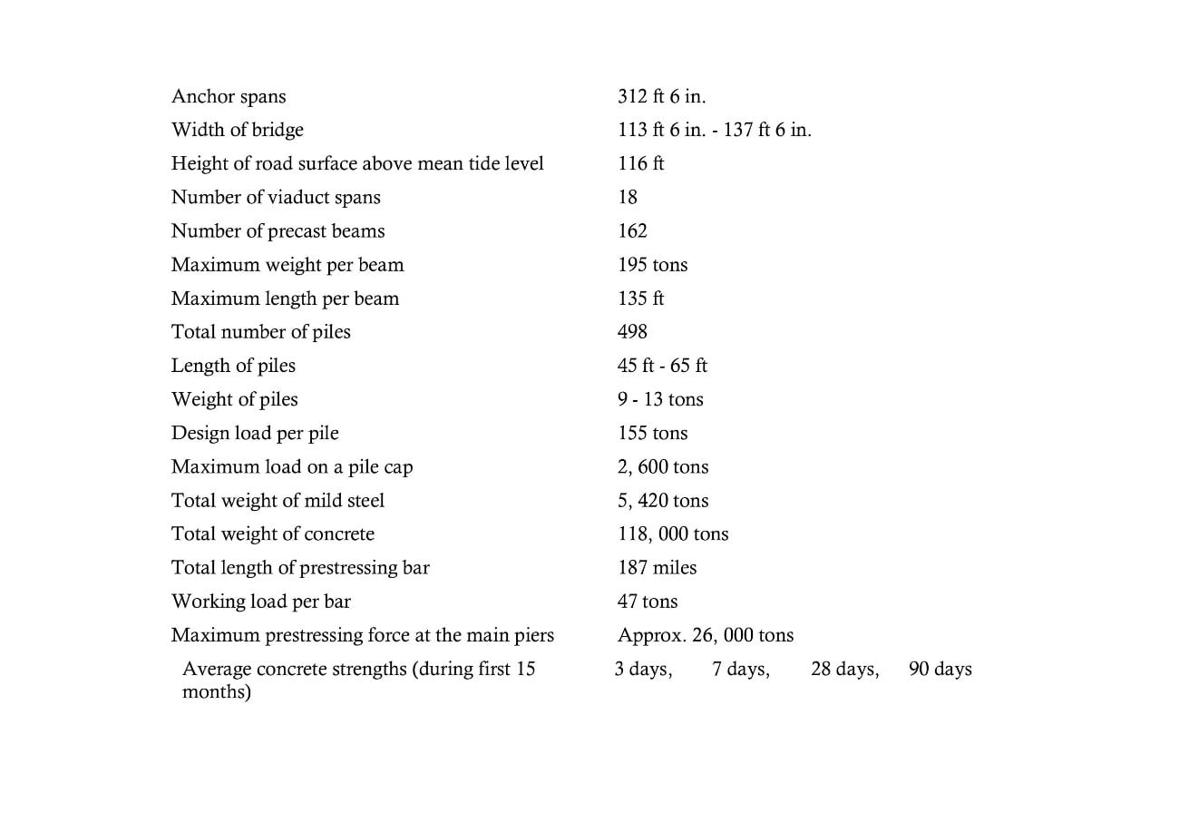
APPENDIX
| Overall length, excluding embankments | 3340 ft |
| Main span | 500 ft |
| Anchor spans | 312 ft 6 in. |
| Width of bridge | 113 ft 6 in. - 137 ft 6 in. |
| Height of road surface above mean tide level | 116 ft |
| Number of viaduct spans | 18 |
| Number of precast beams | 162 |
| Maximum weight per beam | 195 tons |
| Maximum length per beam | 135 ft |
| Total number of piles | 498 |
| Length of piles | 45 ft - 65 ft |
| Weight of piles | 9 - 13 tons |
| Design load per pile | 155 tons |
| Maximum load on a pile cap | 2,600 tons |
| Total weight of mild steel | 5,420 tons |
| Total weight of concrete | 118,000 tons |
| Total length of prestressing bar | 187 miles |
| Working load per bar | 47 tons |
| Maximum prestressing force at the main piers | Approx. 26, 000 tons |
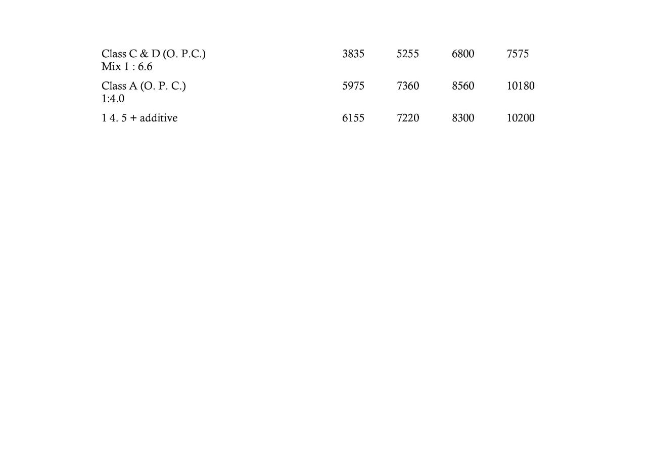
Average concrete strengths (during first 15 months)
| 3 days | 7 days | 28 days | 90 days | |
|---|---|---|---|---|
| Class C & D (O.P.C.) Mix 1:6.6 | 3835 | 5255 | 6800 | 7575 |
| Class A (O.P.C.) 1:4.0 | 5975 | 7360 | 8560 | 10180 |
| 1:4.5 + additive | 6155 | 7220 | 8300 | 10200 |
Printed and published by the Cement and Concrete Association, 52 Grosvenor Gardens London S.W.1, February 1962
Elsewhere on
Roads.org.uk...

New Medway Viaducts
Taken over the course of two years, from 2002 to 2003, these sixteen images chart the construction of two new bridges alongside the M2 Medway Viaduct.