The original length of the M1 ran from Watford, just north of London, to the A5 in Northamptonshire. During the 1960s it was progressively extended north to Yorkshire, but its southern end only made progress further towards London at the very end of the decade.
This booklet was published to mark the opening of the Hendon Urban Motorway, a scheme that carried the M1 south to reach Fiveways Corner, the junction of A1 and A41, just short of the North Circular Road. A further extension to reach the motorway's current southern terminus at the North Circular was added almost a decade later.
This book gives some insight into the planning and construction of an urban motorway that's usually forgotten when major urban roads are discussed, but which was no less disruptive and destructive than others. Running through the North London suburbs, it involved the demolition of rows of neat semi-detached houses, and what's perhaps most remarkable about this book is just how little interest it shows in the environment into which the new road was placed. There are photographs of nightshift engineering work with houses immediately behind, and a lot of detail on the construction of a retaining wall that avoided demolishing two further streets of houses - described in a way that suggests the engineers would rather have just rolled out the wrecking ball.
Page 1
Page 2
Page 3
Page 4
Page 5
Page 6
Page 7
Page 8
Page 9
Page 10
Page 11
Page 12
Page 13
Page 14
Page 15
Page 16
Page 17
Page 18
Page 19
Page 20
Page 21
Page 22
Page 23
Page 24
Page 25

Page 26
Page 27
Page 28
Page 29
Page 30
Page 31
Page 32
Page 33
Page 34
Page 35
Page 36
Page 37
Page 38
Page 39
Page 40
Page 41
Page 42
Page 43
Page 44
Page 45
Page 46
Page 47
Ministry of Transport: Hendon Urban Motorway: Southern Extension of the M1
Consultants to the Ministry of Transport for the Hendon Urban Motorway: W.S. Atkins & Partners
Main Contractors:
- Messrs. Holland & Hannen and Cubitts (Civil Engineering) Ltd
- The Cementation Company Ltd
- Messrs. Maples, Ridgway & Partners Limited
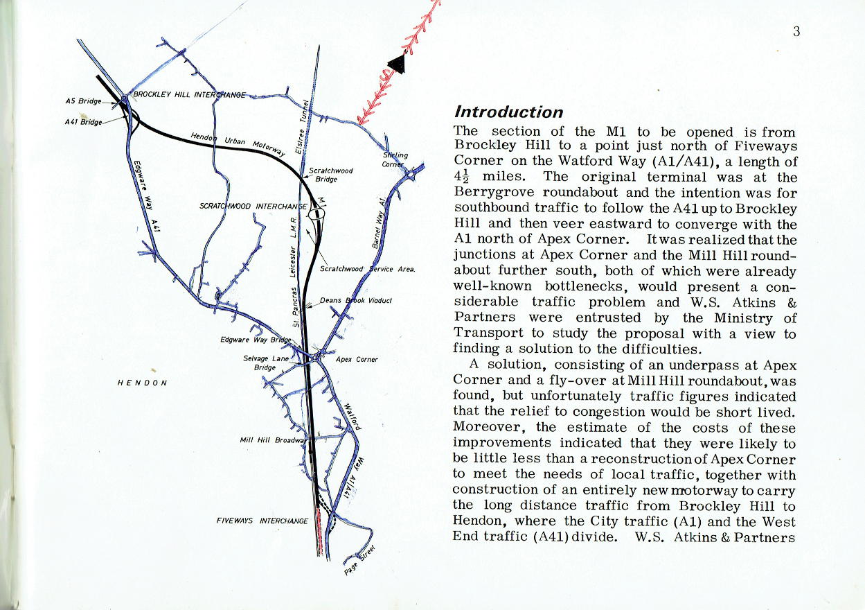
Introduction
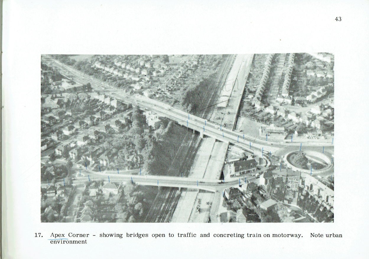
The section of the M1 to be opened is from Brockley Hill to a point just north of Fiveways Corner on the Watford Way (A1/A41), a length of 4½ miles. The original terminal was at the Berrygrove roundabout and the intention was for southbound traffic to follow the A41 up to Brockley Hill and then veer eastward to converge with the A1 north of Apex Corner. It was realized that the junctions at Apex Corner and the Mill Hill roundabout further south, both of which were already well-known bottlenecks, would present a considerable traffic problem and W.S. Atkins & Partners were entrusted by the Ministry of Transport to study the proposal with a view to finding a solution to the difficulties.
A solution, consisting of an underpass at Apex Corner and a fly-over at Mill Hill roundabout, was found, but unfortunately traffic figures indicated that the relief to congestion would be short lived. Moreover, the estimate of the costs of these improvements indicated that they were likely to be little less than a reconstruction of Apex Corner to meet the needs of local traffic, together with construction of an entirely new motorway to carry the long distance traffic from Brockley Hill to Hendon, where the City traffic (A1) and the West End traffic (A41) divide. W.S. Atkins & Partners were accordingly instructed to proceed forthwith with the re-design of Apex Corner roundabout and, at the same time, examine alternative possibilities and recommend a route for the Hendon Urban Motorway extending from the Hertfordshire border just north of Brockley Hill to north of Five-ways Corner, Hendon. The section of the motorway between the Berrygrove roundabout and the Hertfordshire border was entrusted to Hertfordshire County Council. The Hertfordshire section (33 miles) was opened in October 1966.
Factors
In rural motorways, as in most other engineering projects, the planning and design are mostly governed by compliance with the specification and by costs. In urban motorways
(of which the Hendon Motorway is the first), such factors as the avoidance of demolition of property, the preservation of local amenities and aesthetics are at least of equal importance. The Consulting Engineers were accordingly instructed to take all such considerations into account in the planning of the Motorway.
Another factor of great importance in urban motorways is the future development of the area through which they pass and the consequent need to provide for the future in the present design. Here again extra costs can be entailed and in fact have been accepted by the Ministry in order not to jeopardize the future of Hendon. All these can be regarded as special features and the more important examples are referred to below.
The Route
Four possible alternative routes were studied initially and the present line was selected because it satisfied the requirements to a much greater extent than the others. Three further modifications of generally the same route and four other alternatives (all suggested by third parties) were likewise examined, but none offered greater advantages than the original choice, which, it is of interest to note, adheres closely to the line suggested by Baker and Glanville (J.F.A. Baker, C.B., M.I.C.E., M.I. Mun. E., the then Director of Highway Engineering, M. of T.; Sir William Glanville, C.B., C.B. E., D. Sc., Ph.D., F.R. S., the then Director of the R.R.L.) in their paper 'Urban Motorways in Great Britain' presented to the British Road Federation conference on Urban Motorways in 1956.
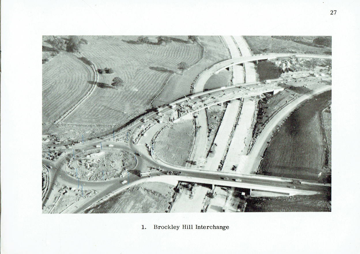
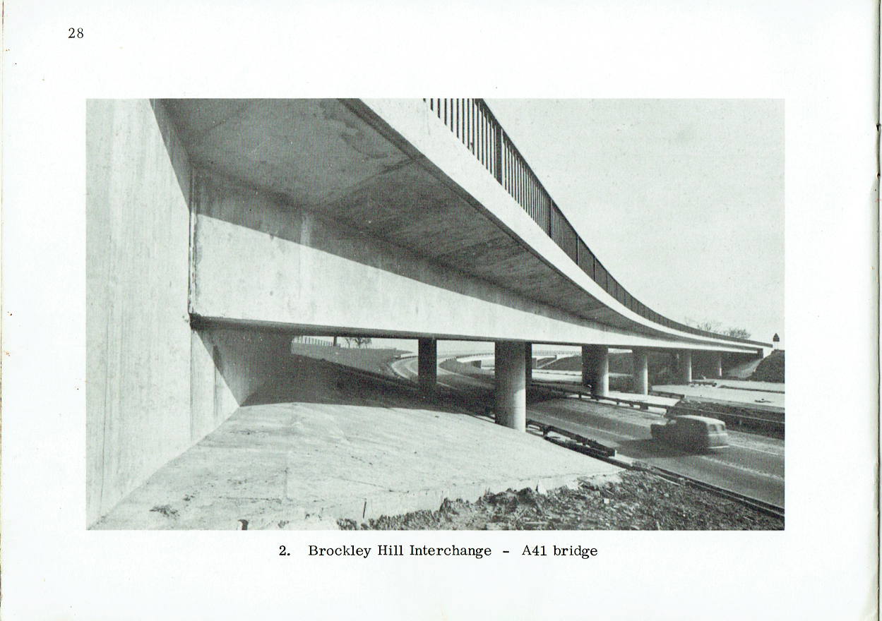
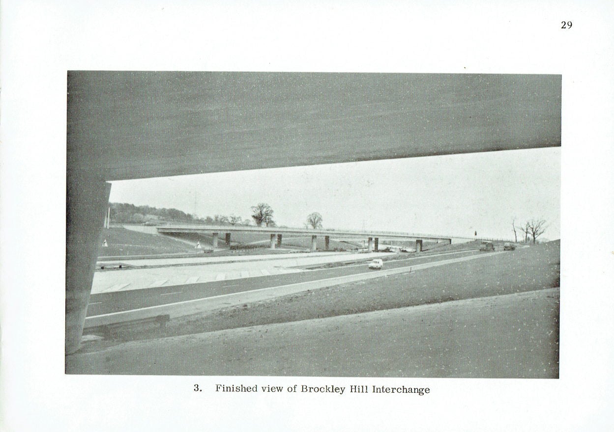
Brockley Hill Interchange
The extent of the Hendon Urban Motorway is shown on the map and this includes a portion of some 1½ miles, between Brockley Hill and Scratch-wood, which is built to rural motorway standards. The interchange at Brockley Hill is of the partial type, access to the motorway being limited to traffic wishing to travel north: this precludes the local commuter traffic from saturating the motorway at peak hours. Of the three bridges at this interchange, that carrying the A41 trunk road is of particular interest. The angle of skew is more than 450° and the attendant difficulty was resolved by the use of a separate bridge for each carriageway, each carried on simple round columns. Both bridges are of in situ post tensioned concrete and the design was checked by means of an electronic computer. The other two bridges, one carrying the A5 trunk road and the other the south-bound slip road, consist of precast post tensioned concrete decks carried on in situ wall piers.
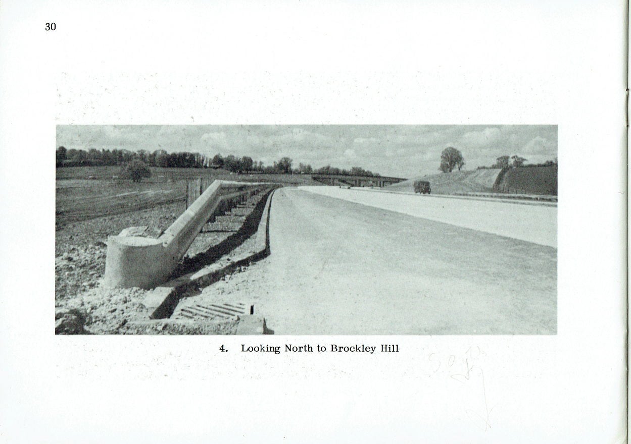
Brockley Hill to Scratchwood
The length of motorway between Brockley Hill and Scratchwood contains two special features. The first consists of the motorway being carried largely in cutting at depths of up to 40 ft. with the object of preserving the aesthetics of the 'open space' area. A number of alternative horizontal and vertical alignments were accordingly examined from every point of view. The second special feature is the provision of a bridge 29 ft. between parapets carrying what was little more than a path (Edgwarebury Lane), to allow for future development of the area. The bridge is of cellular construction post tensioned concrete with a central span of 120 ft.
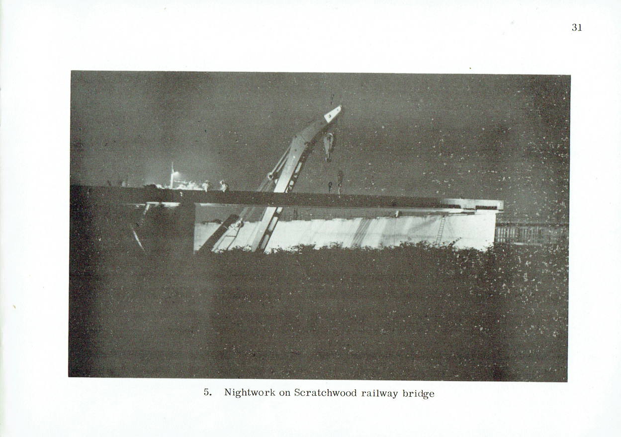
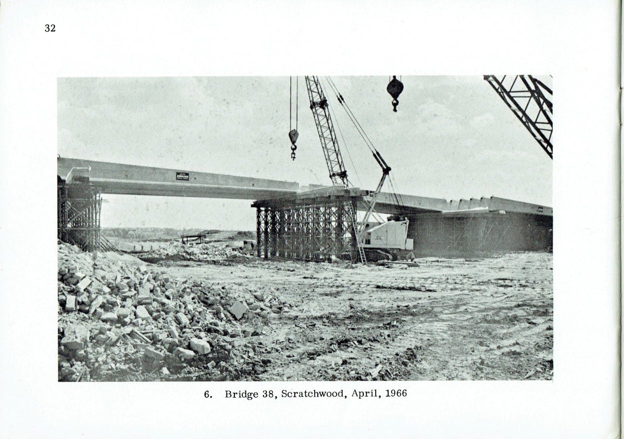
The crossing of the St. Pancras-Leicester main line takes place just south of Scratchwood tunnel via the Scratchwood bridge, a four span continuous structure consisting of Preflex beams and a reinforced concrete deck slab. Composite action is induced by horseshoe shear connectors welded to the steel beams prior to preflection which, incidentally, reduces the possibility of brittle fracture. The skew of the bridge is 44° and the length (skew spans) is 254 ft.
Maintenance and Service Area
Immediately after the crossing, the motorway swings southward to run alongside the railway at Deansbrook, and the area between the road and the railway is intended to be utilized for a maintenance compound and a service area. Both are adjacent to a standard oval type of two level interchange required for considerations of future planning. The two bridges carrying the roundabout over the motorway are similar to the Edgwarebury Lane bridge.
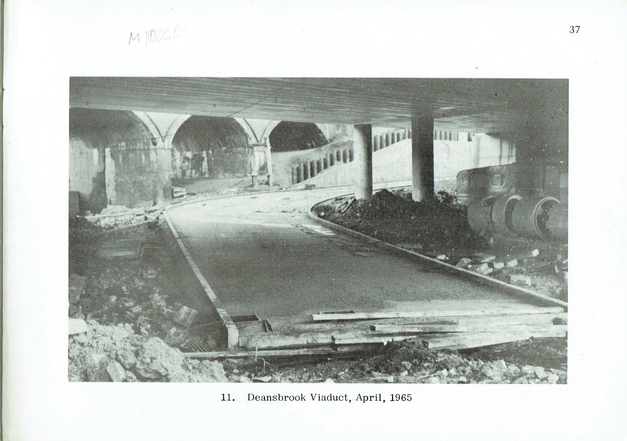
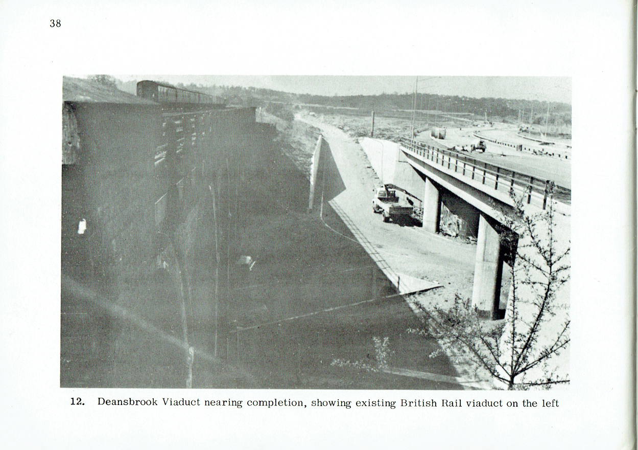
Deansbrook Viaduct
The crossing of Deansbrook and the access road to Scratchwood is achieved by means of the Deansbrook viaduct, a three span structure 177 ft. long with a continuous deck of precast pretensioned units carried on circular piers.
Deansbrook to Mill Hill
The transition from rural to urban motorway standard takes place just north of Deansbrook and from there southward the motorway runs alongside the railway with an overall width generally reduced from 129 ft. to 111 ft. 6 in., apart from one or two 'pinch points' where a further decrease in width is made by reducing the hard shoulders from 10 ft. to 8 ft. The special features of the stretch between Deansbrook and Mill Hill Broadway consist of a retaining wall of up to 40 ft. in height, the widening of the Edgware Way and the reconstruction of Selvage Lane bridges.
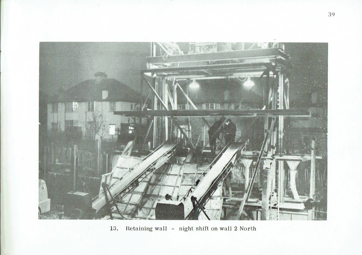
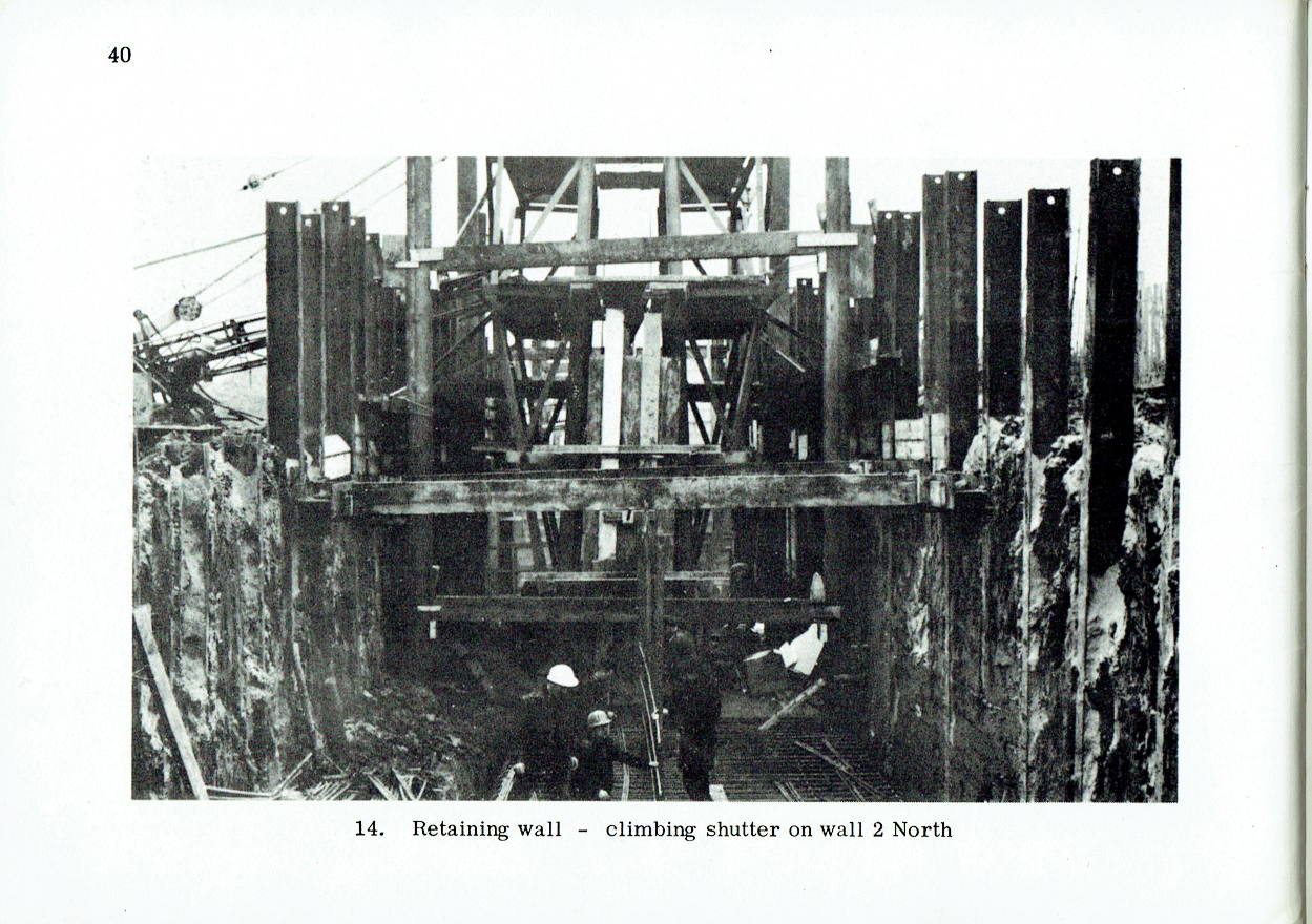
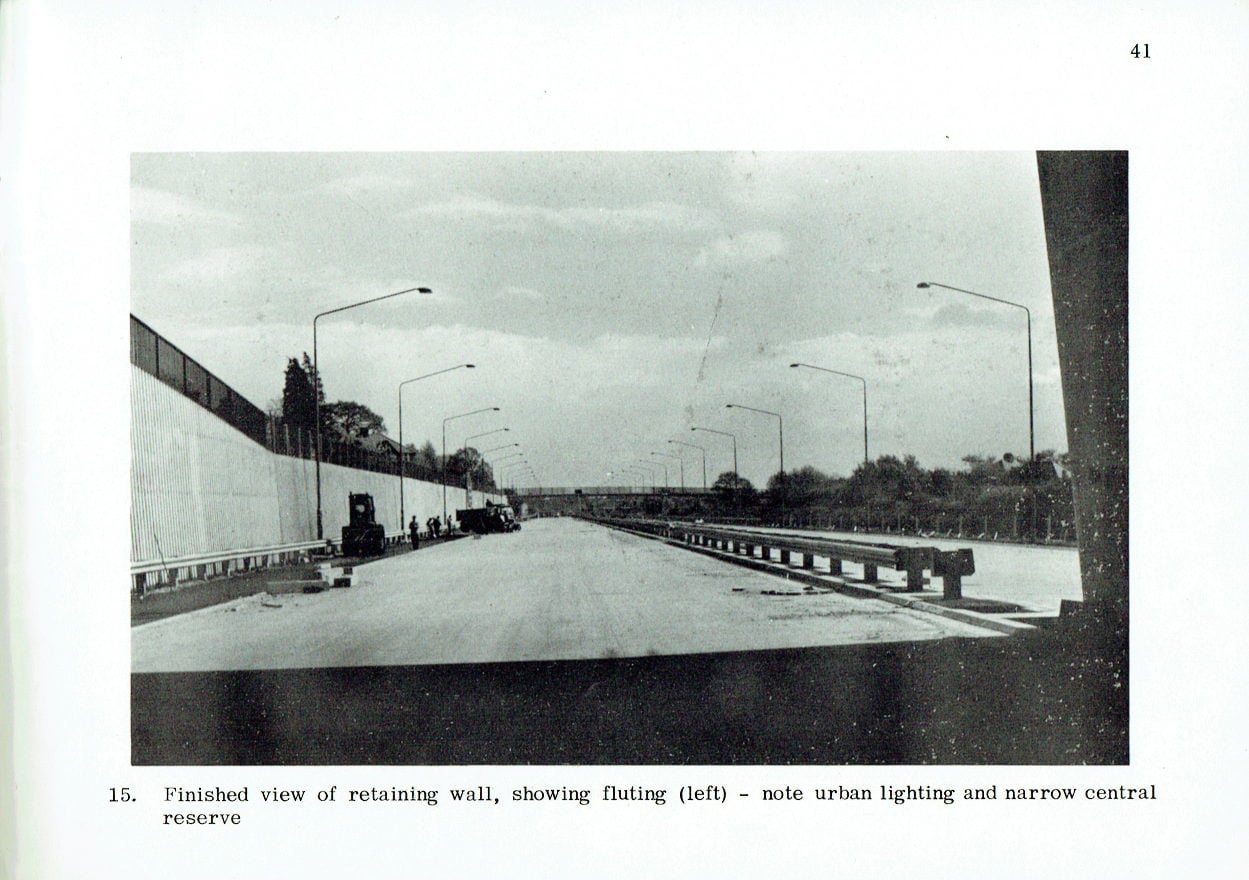
Retaining Wall
The motorway retaining wall is some 12 miles in length and its adoption was dictated entirely by the desire to avoid the complete demolition of two streets of residential houses, shops, etc. This structure, built on London Clay, presented one of the biggest engineering problems of the whole project and the advice of Prof. A. W. Skempton, D.Sc., F.R.S., M.I.C. E., one of the world's accepted authorities on this kind of soil, was obtained in connection with the design. The decision to adopt the construction of a retaining wall seriously complicated both the design and construction of this section of the motorway, but the extra costs and difficulties were accepted in order to avoid wholesale hardship to residents and disruption of local amenities. Even so, unfortunately it was not physically possible to save the west side of Glendor Gardens. A smaller retaining wall is also provided between the railway and the motorway in places where the latter runs below the toe of the railway embankment.
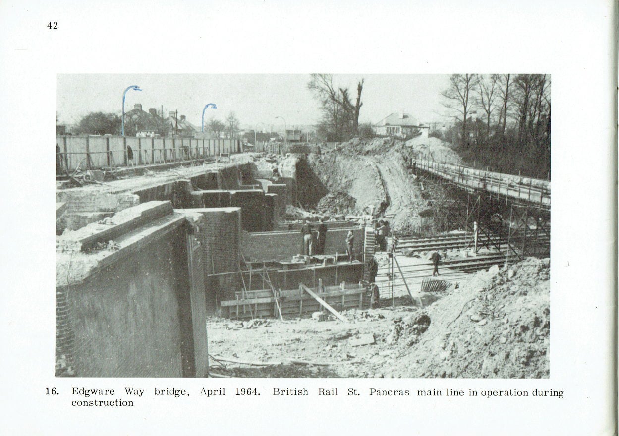
Edgware Way Bridge
The A41 trunk road was carried over the railway just west of Apex Corner by a reinforced concrete bridge only 40 years old and in relatively good condition. In the interest of economy it was decided to make use of the existing structure and extend it to go over the motorway. It was also decided to widen both new and old portions of the bridge to allow for the future dualling of the A41 trunk road.
The widening itself presented no difficulties but care was taken to harmonize the appearance of the old and new work. The precast pretensioned deck with in situ concrete in-filling is supported on piers the foundations of which have been piled to reduce the effects of differential settlement. The so-called anchor pier between the old and new bridges has been designed in its massive form to afford a definite architectural break at this point. It has also enabled the piling for the new foundations to be kept well clear of the old.
Selvage Lane Bridge
The bridge carrying the A5109 over the railway was 25 ft. wide between parapets with a road width of only 19 ft., which, together with curved approaches, resulted in a bottleneck. This was another instance where it was decided that the design of the motorway must take into account the future development of the locality and, in addition, the reconstruction was done without closing the road to traffic in either direction.
The new bridge is 50 ft. wide between parapets and passes over the railway and the motorway in four spans totalling 230 ft. The bridge is founded on bored piles that have been sited sufficiently far from the railway tracks to avoid speed restrictions. The deck consists of precast pretensioned box beams placed in two stages and stressed together with Macalloy bars. The deck is supported on wall type piers which are shaped architecturally.
Lilley Lane Footbridge
A pedestrian right of way between Selvage Lane and Mill Hill Broadway was carried over the railway on an old brick arch bridge which was already in a poor condition consequent on the slip, towards the railway, of both sides of the clay cutting. The structure already contained a number of cracks and the removal of the end span (to make room for the motorway) would have rendered it unstable. The right of way has been preserved, as requested by the then Hendon Borough Council, and the entirely new footbridge consists of precast post tensioned trough section concrete beams supported on reinforced concrete piers. The beams are simply supported, the maximum span weighing 35 tons, and a system of interlocking bearings being used in order to reduce the width of the piers.
Mill Hill Broadway
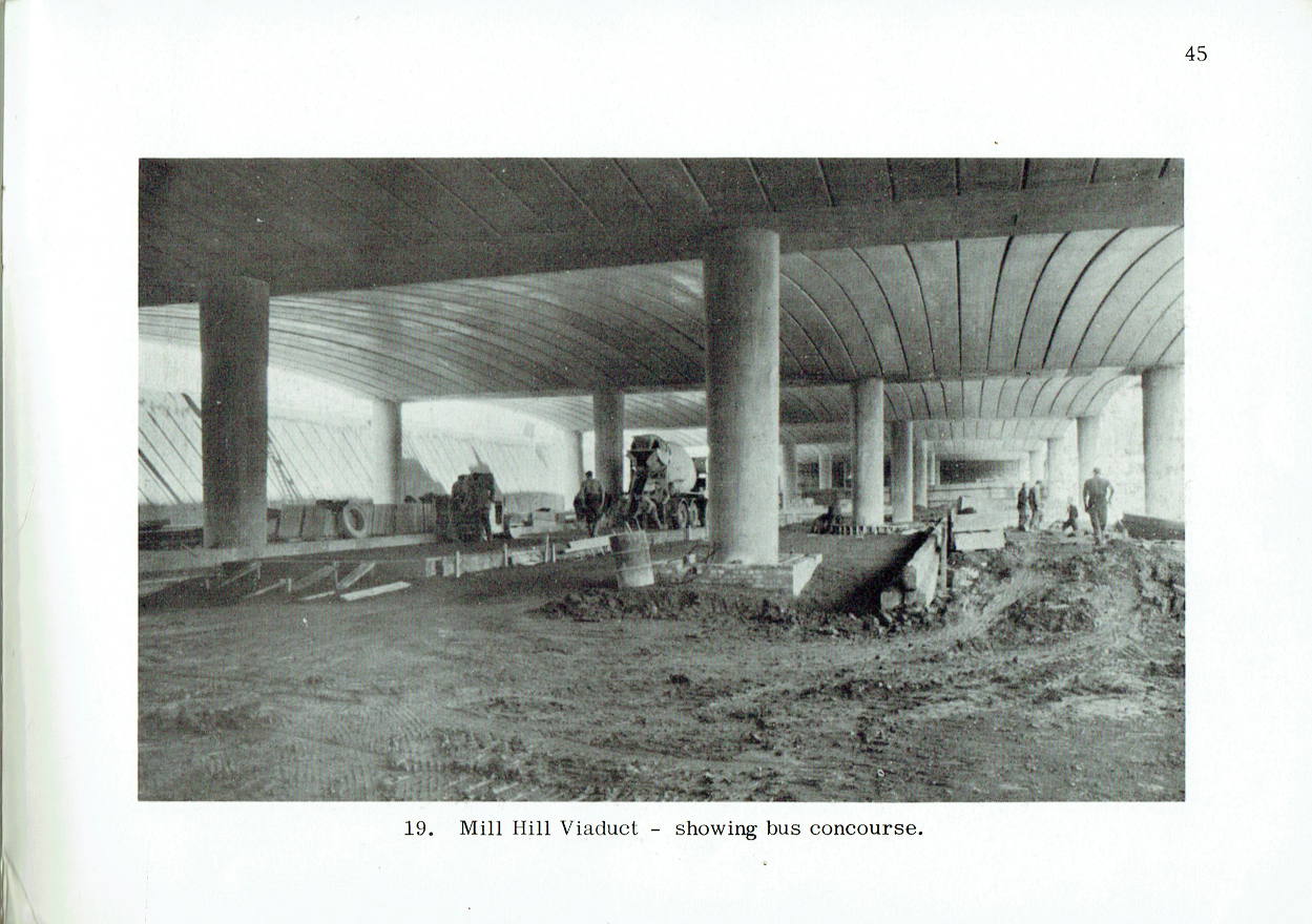
The most pronounced effect of the previously mentioned special factors applicable to the design of the urban motorways can be seen in the Mill Hill Broadway area, which is the main shopping and transport centre of the district. The old Broadway kinked on its approach to the railway and was crossed by the main line via two bridges of only 20 ft. in road width and with a headroom of only 13 ft. at the crown. Traffic congestion was the inevitable result and public transport was seriously hampered by having to use single deck buses. The building of the motorway over the existing layout of the Broadway would have perpetuated these conditions; on the other hand, here was an opportunity not only to improve the alignment of the main street but also to provide a closer link between bus and rail services.
The Broadway has been straightened and now passes under a viaduct carrying the motorway and under two new railway bridges, all three with the normal statutory clearance, and with the roadway increased in width to dual 20 ft. carriageway. This eliminates all restrictions on the type of vehicle able to use the Broadway. The bus terminal, formerly in the open in front of the station, has been moved under cover beneath the viaduct, and the station has been reconstructed with the East entrance opening directly into the covered bus terminal. Steps are provided from the realigned Station Road to give the inhabitants to the east of the railway direct access to both the station and the bus terminal, and the station itself is now planned so that passengers have access to any platform by means of an access tunnel at the same level as the east side booking office.
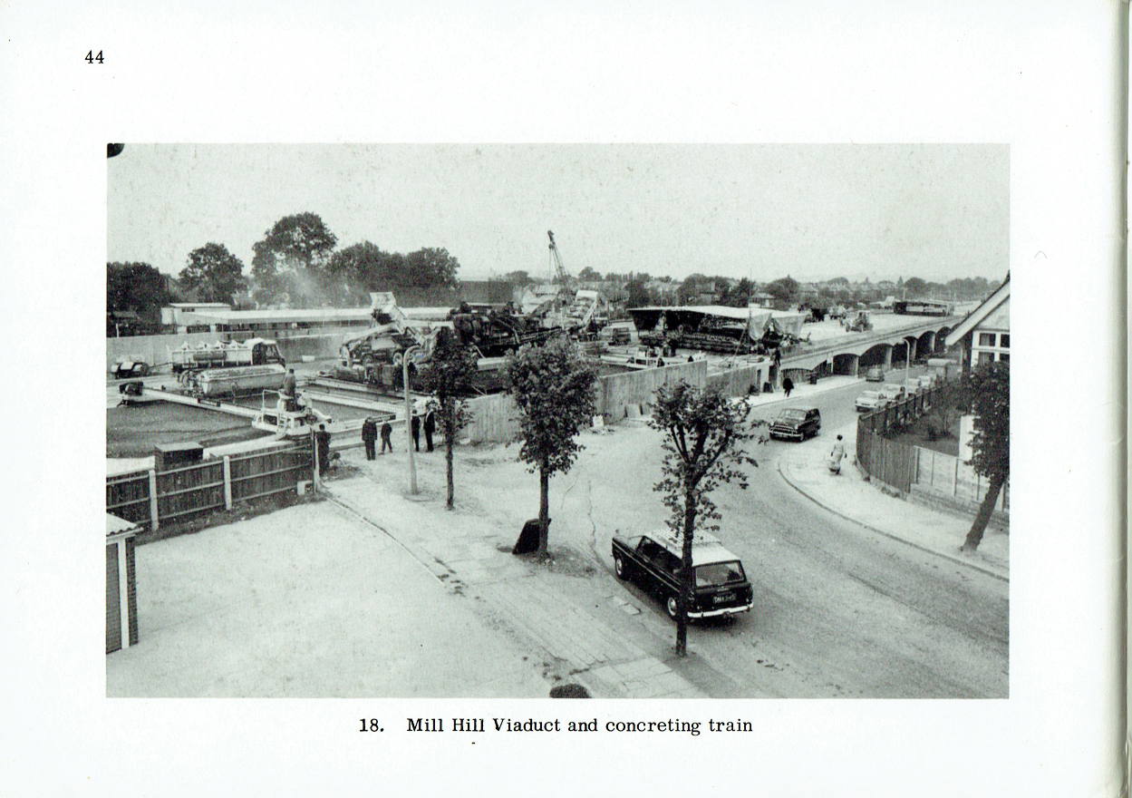
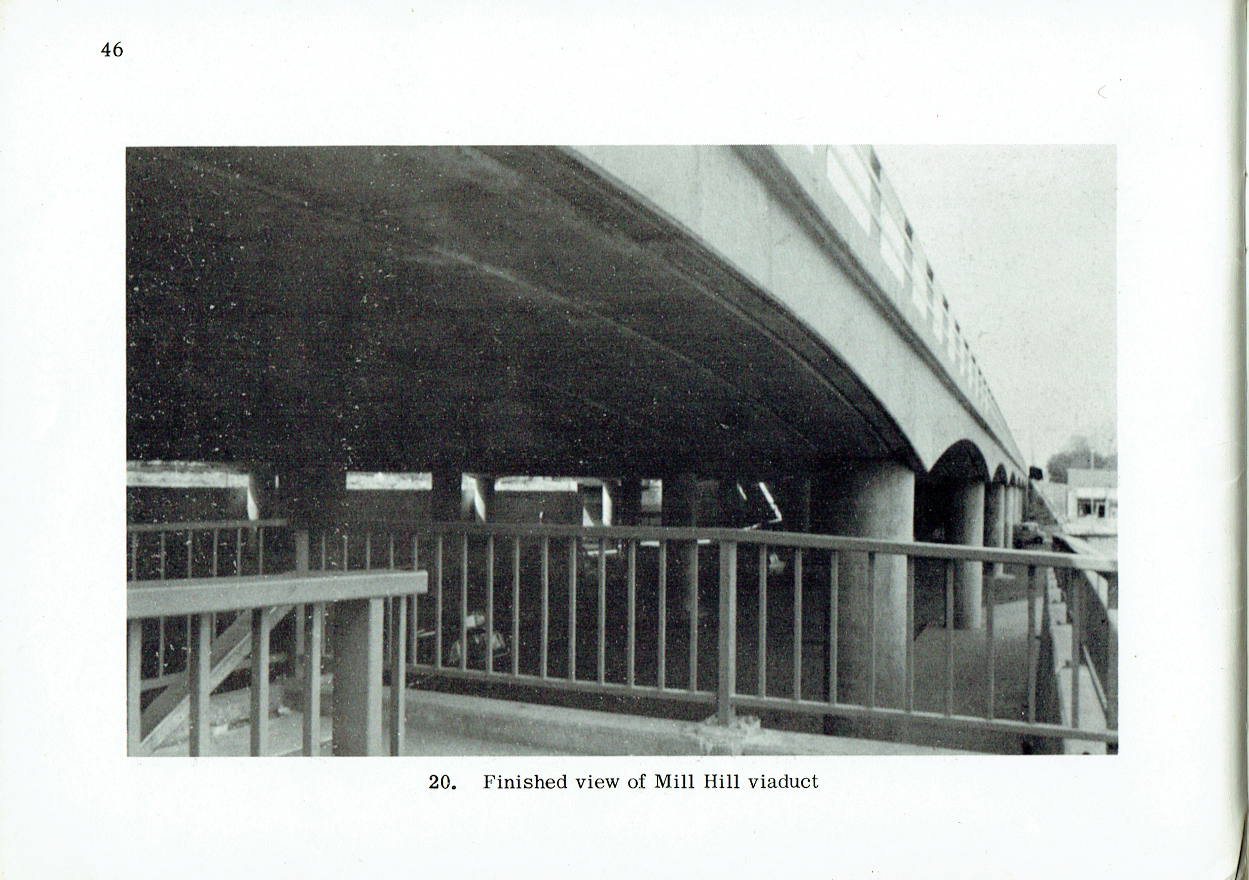
Mill Hill Viaduct
The structure shown in fig. 20 is 476 ft. long, and is supported on circular concrete columns arranged in sets of four across the viaduct, the setting out being governed by the required turning circles for the bus terminal. The deck structure is composed of precast post-tensioned concrete beams of varying cross section which span 68 ft. on to cast in situ transverse beams. In view of its location, aesthetic considerations played an important part in the design of the viaduct.
Mill Hill Railway Bridges
The two new bridges consist of welded steel trapezoidal box girders with concrete encased steel decks. The south abutment is designed to similar criteria as the motorway retaining walls, but it was necessary to adopt a type of beam and column construction for the north abutment because the proximity of the existing bridge left no room for the building of a conventional retaining wall.
In addition, a further complication arose because the stability of the existing brick arch railway bridge would have been affected by the adjacent new works. This arch bridge therefore had to be first replaced by a British Rail standard Type A underline bridge, and the change-over was accomplished in one week-end occupation. Both the Type A bridge and the second (existing) bridge will be eventually removed and replaced by an embankment to save future maintenance.
Mill Hill to Fiveways
South of Mill Hill Broadway, the motorway continues along the railway gradually rising to cross Bunns Lane and then connect to the A1/A41 road north of Fiveways Corner by means of temporary slip roads. The crossing of the Finchley and Edgware railway line is by means of an embankment since this line has now been abandoned. This closure of the line has also enabled the southbound slip road to be aligned along the railway cutting and pass under Watford Way (A1/A41 road) by means of the existing bridge.
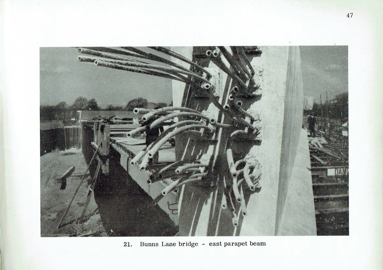
Bunns Lane Bridge
This is the last new bridge in the present construction and consists of a 57° skew solid slab concrete bridge. The present headroom is 13 ft. 6 in. (similar to that of the adjacent railway bridge) but the new bridge foundations have been constructed to allow for the headroom to be increased to the full 16 ft. 6 in. statutory clearance at some later date.
Future Extension
The present terminal north of Fiveways Corner is of a purely temporary nature and, in fact, a traffic investigation has shown that it will remain adequate for only a comparatively short time. The ultimate short-term aim is to extend the motorway alongside the railway line to the North Circular Road and to provide a permanent partial interchange at Fiveways Corner with the A1 only, to cope with the City and docks traffic. Traffic bound for the West End will then continue along the motorway to the terminal on the North Circular Road and traffic congestion at this point will be eased by the provision of a complex at Staples Corner. It will be appreciated that the problem of this intersection is complicated by the fact that it will be situated at the junction of two main trunk roads and will thus be required to separate the various categories of traffic from the motorway, the North Circular Road and the Edgware Road. Further dispersion will be afforded by the nearby Brent Cross three-level interchange and the projected Finchley Road improvements. Provision has been made in the design of the motorway terminal for a possible further extension of the M1 southwards.
Design Standards
The motorway is designed to the Ministry of Transport specifications for Rural and Urban
Motorways. The main difference is the reduction of the overall width from 129 ft. for the rural to 111 ft. 6 in. for the urban motorway, this being achieved at the expense of the verges and the central reserve. A further reduction of 2 ft. in the width of each hard shoulder is also allowed at pinch points in urban areas and the urban section will be lit by colour corrected mercury lanterns mounted on 40 ft. high columns. The type and thickness of pavements is governed largely by the ground conditions and the Hendon Motorway is of the rigid type consisting generally of an 11 in. reinforced concrete slab resting on a 6 in. lean mix base.
The 11 in. thick mesh reinforced concrete carriageway pavement is designed to permit laying by a 'concrete train' supported by reinforced concrete 'bankettes' which form the permanent margins of the motorway and allow construction of the whole 36 ft. carriageway in one operation. The 'bankettes' are dowelled into the carriageway paving. Expansion joints in the paving are provided at 240 ft. intervals with intermediate contraction joints.
The total depth of construction including for paving foundation is therefore 23 in. designed in accordance with stability characteristics of the sub-grade and the traffic loading and usage. Correspondingly the hard shoulders comprise a 22½ in. construction depth consisting of a 2 in. bitumen macadam surfacing on a lean mix concrete base placed on a 6 in. sub-base.
The motorway is built on London Clay, a somewhat treacherous material at best, and, moreover, of a variable nature throughout the length of the motorway. To allow for this and to enable the pavement and base to be kept of uniform thickness, a 6 in. sub-base is provided. This consists of burnt red ash, considerable quantities of which occur in the Scratchwood area. Even so, large amounts of excavated material and of local soft spots have been discarded as entirely unsuitable material.
Apart from Lilley Lane footbridge and the Edgwarebury Lane bridge, all bridges are designed for Ministry of Transport abnormal loading. The exception of Edgwarebury Lane bridge has been made because it is not anticipated that the lane will ever become anything more than a local road in a residential and green belt district; this bridge has accordingly been designed to carry the standard Ministry loading.
The large retaining walls, as already mentioned, have been designed on the basis of a special soil investigation and the consequent recommendations of Professor A.W. Skempton, D.Sc., F.R.S., M.I.C.E.
Effect of Urban Conditions
The effect on local residents of such a major works was taken into account in the design and the contract documents included clauses specifying how the work was to be done, which is by no means usual. The biggest nuisance was noise and particularly that due to pile driving. To reduce this to a minimum, the vast majority of the excavations were upheld either by the use of broad flange beam king piles lowered into bored holes or by the use of the noiseless Taylor Woodrow 'Taywood' hydraulic equipment for the driving and extraction of steel sheet piling. In a very small number of isolated instances neither method could be used and in such cases the conventional driving of sheet piling was restricted to normal working hours.
Another instance of a similar kind was the demolition of the old Selvage Lane bridge. Following representations from the local residents this structure was demolished piecemeal rather than by explosives.
The detailed forward planning of the works made long-term diversions or street closures unnecessary, and all earth movement by road was discussed and agreed both with the police and the local authority. Particular attention was paid to the question of mud on roads, which is inevitable in earth moving operations on a large scale, and special measures to keep this nuisance to a minimum and to clean roads were in force. Even so, it was not possible to avoid some inconvenience to the local residents, but all efforts were made to reduce this as far as practicable.
Organization and Costs
The two main factors influencing the programme were the need to give one year's notice for railway possession of the main line and the difficulties of land acquisition in urban areas, especially where controlled tenants were involved. Another vital consideration was for the Brockley Hill interchange to be completed at the same time as the Hertfordshire section of the motorway, since this section could not be put into service without it.
It is not usual to split up into several contracts a length of only 42 miles of motorway, but this was decided upon in view of the special circumstances and the effect which delays on one part of the motorway could have on a single contract.
The work was accordingly split up and let in three separate main contracts:
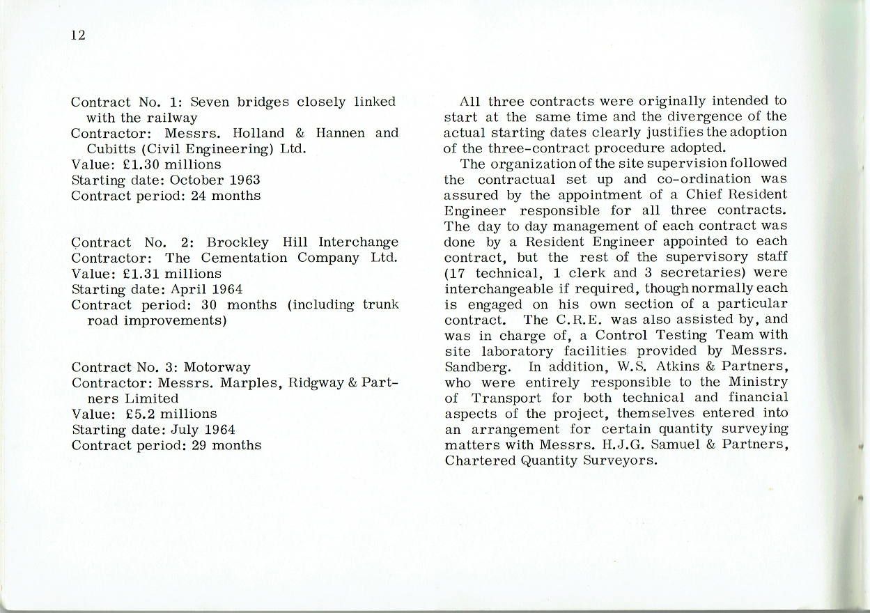
Contract No. 1: Seven bridges closely linked with the railway
- Contractor: Messrs. Holland & Hannen and Cubitts (Civil Engineering) Ltd.
- Value: £1.30 millions
- Starting date: October 1963
- Contract period: 24 months
Contract No. 2: Brockley Hill Interchange
- Contractor: The Cementation Company Ltd.
- Value: £1.31 millions
- Starting date: April 1964
- Contract period: 30 months (including trunk road improvements)
Contract No. 3: Motorway
- Contractor: Messrs. Marples, Ridgway & Partners Limited
- Value: £5.2 millions
- Starting date: July 1964
- Contract period: 29 months
All three contracts were originally intended to start at the same time and the divergence of the actual starting dates clearly justifies the adoption of the three-contract procedure adopted.
The organization of the site supervision followed the contractual set up and co-ordination was assured by the appointment of a Chief Resident Engineer responsible for all three contracts. The day to day management of each contract was done by a Resident Engineer appointed to each contract, but the rest of the supervisory staff (17 technical, 1 clerk and 3 secretaries) were interchangeable if required, though normally each is engaged on his own section of a particular contract. The C.R.E. was also assisted by, and was in charge of, a Control Testing Team with site laboratory facilities provided by Messrs. Sandberg. In addition, W.S. Atkins & Partners, who were entirely responsible to the Ministry of Transport for both technical and financial aspects of the project, themselves entered into an arrangement for certain quantity surveying matters with Messrs. H.J.G. Samuel & Partners, Chartered Quantity Surveyors.
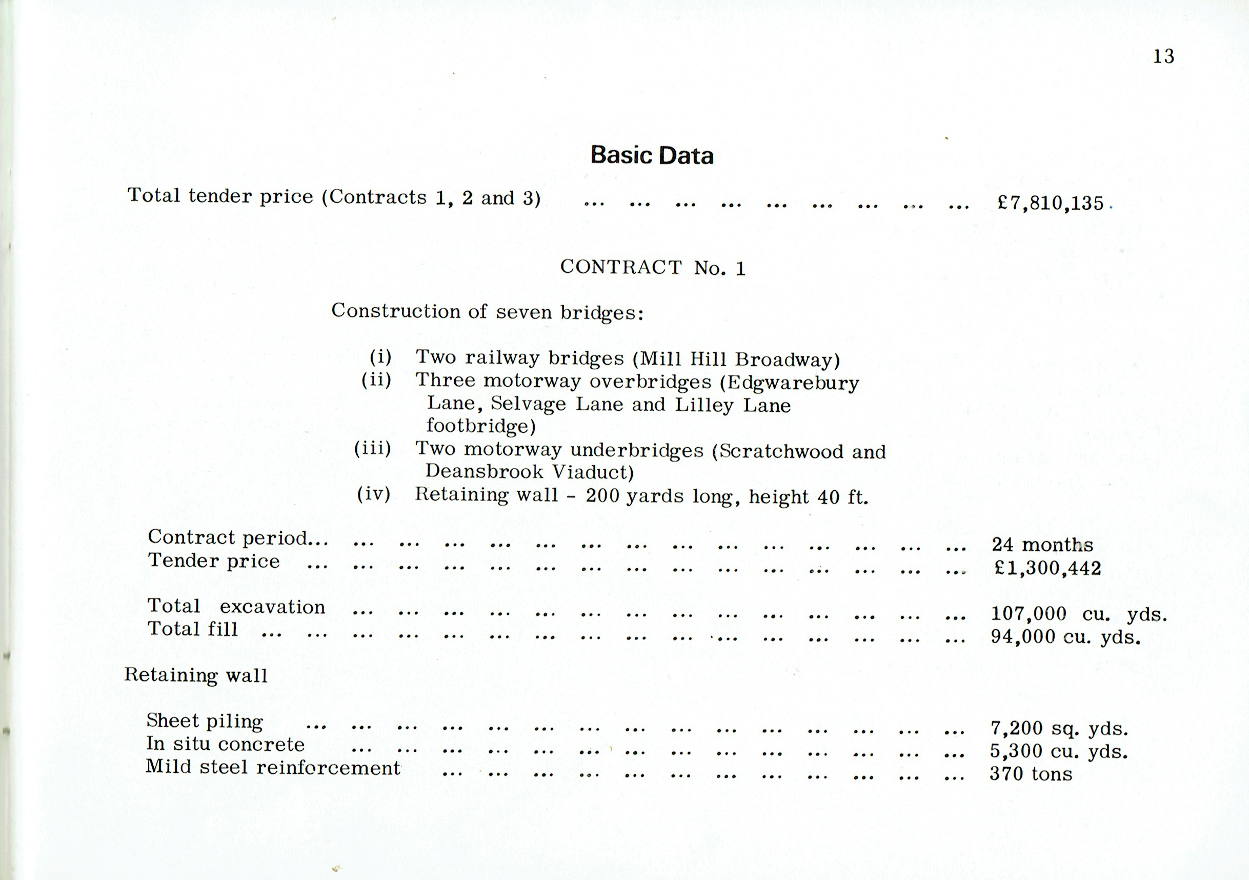
Basic Data
Total tender price (Contracts 1, 2 and 3): £7,810,135
CONTRACT No. 1
Construction of seven bridges:
- Two railway bridges (Mill Hill Broadway)
- Three motorway overbridges (Edgwarebury Lane, Selvage Lane and Lilley Lane footbridge)
- Two motorway underbridges (Scratchwood and Deansbrook Viaduct)
- Retaining wall - 200 yards long, height 40 ft.
| Contract period | 24 months | |
| Tender price | £1,300,442 | |
| Total excavation | 107,000 cu. yds. | |
| Total fill | 94,000 cu. yds. | |
| Retaining wall | Sheet piling | 7,200 sq. yds. |
| In situ concrete | 5,300 cu. yds. | |
| Mild steel reinforcement | 370 tons | |
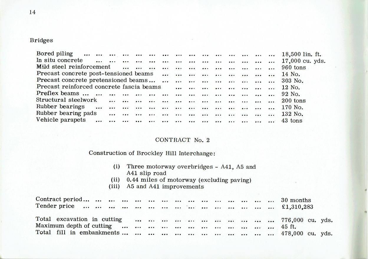
| Bridges | Bored piling | 18,500 lin. ft. |
| In situ concrete | 17,000 cu. yds. | |
| Mild steel reinforcement | 960 tons | |
| Precast concrete post-tensioned beams | 14 No. | |
| Precast concrete pretensioned beams | 303 No. | |
| Precast reinforced concrete fascia beams | 12 No. | |
| Preflex beams | 92 No. | |
| Structural steelwork | 200 tons | |
| Rubber bearings | 170 No. | |
| Rubber bearing pads | 132 No. | |
| Vehicle parapets | 43 tons | |
CONTRACT No. 2
Construction of Brockley Hill Interchange:
- Three motorway overbridges - A41, A5 and A41 slip road
- 0.44 miles of motorway (excluding paving)
- A5 and A41 improvements
| Contract period | 30 months | |
| Tender price | £1,310,283 | |
| Total excavation in cutting | 776,000 cu. yds. | |
| Maximum depth of cutting | 45 ft. | |
| Total fill in embankments | 478,000 cu. yds. | |
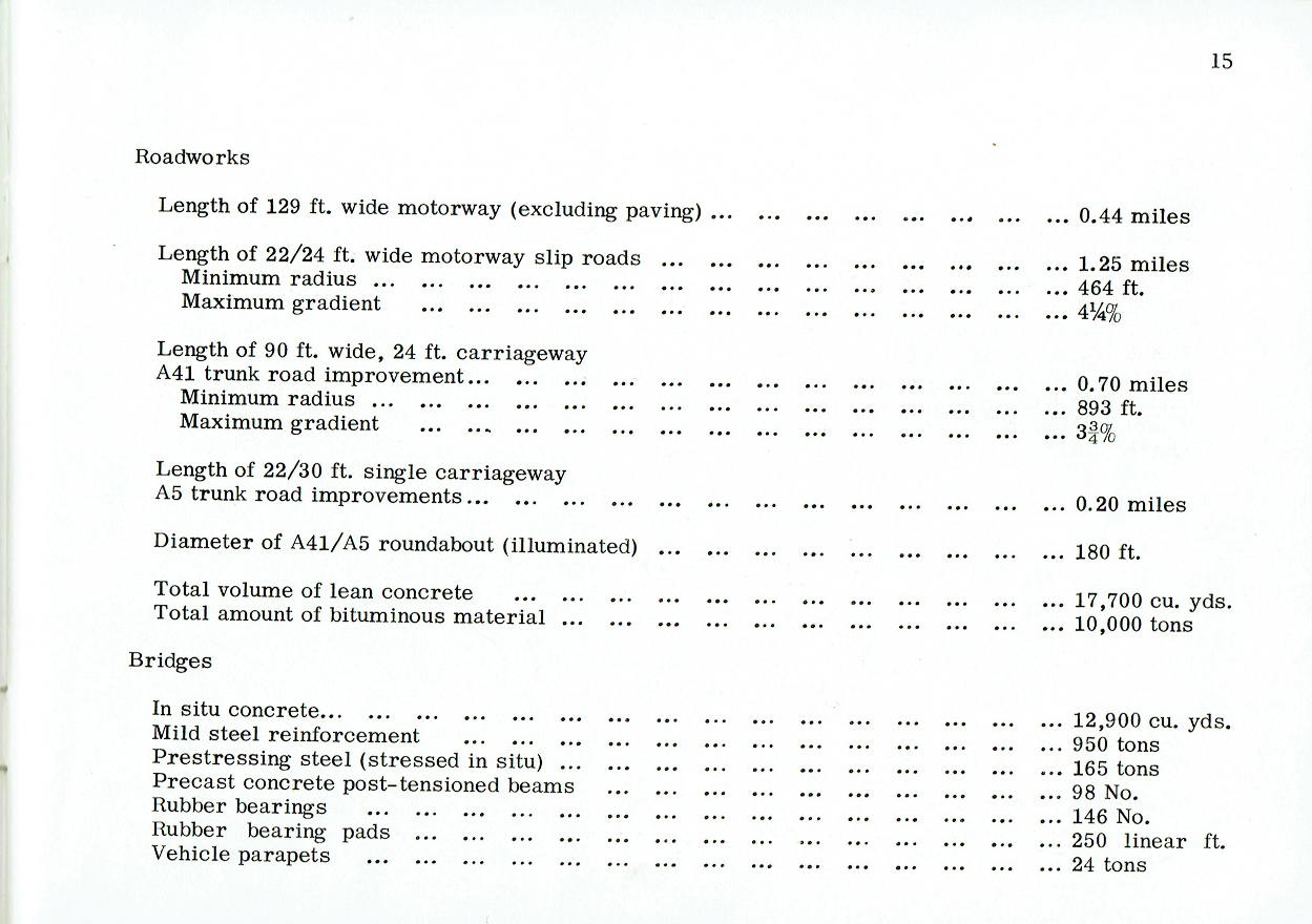
| Roadworks | Length of 129 ft. wide motorway (excluding paving) | 0.44 miles |
| Length of 22/24 ft. wide motorway slip roads | 1.25 miles | |
| Minimum slip road radius | 464 ft. | |
| Maximum slip road gradient | 4¼% | |
| Length of 90 ft. wide, 24 ft. carriageway: A41 trunk road improvement | 0.70 miles | |
| Minimum trunk road radius | 893 ft. | |
| Maximum trunk road gradient | 3¾% | |
| Length of 22/30 ft. single carriageway: A5 trunk road improvements | 0.20 miles | |
| Diameter of A41/A5 roundabout (illuminated) | 180 ft. | |
| Total volume of lean concrete | 17,700 cu. yds. | |
| Total amount of bituminous material | 10,000 tons | |
| Bridges | In situ concrete | 12,900 cu. yds. |
| Mild steel reinforcement | 950 tons | |
| Prestressing steel (stressed in situ) | 165 tons | |
| Precast concrete post-tensioned beams | 98 No. | |
| Rubber bearings | 146 No. | |
| Rubber bearing pads | 250 linear ft. | |
| Vehicle parapets | 24 tons | |
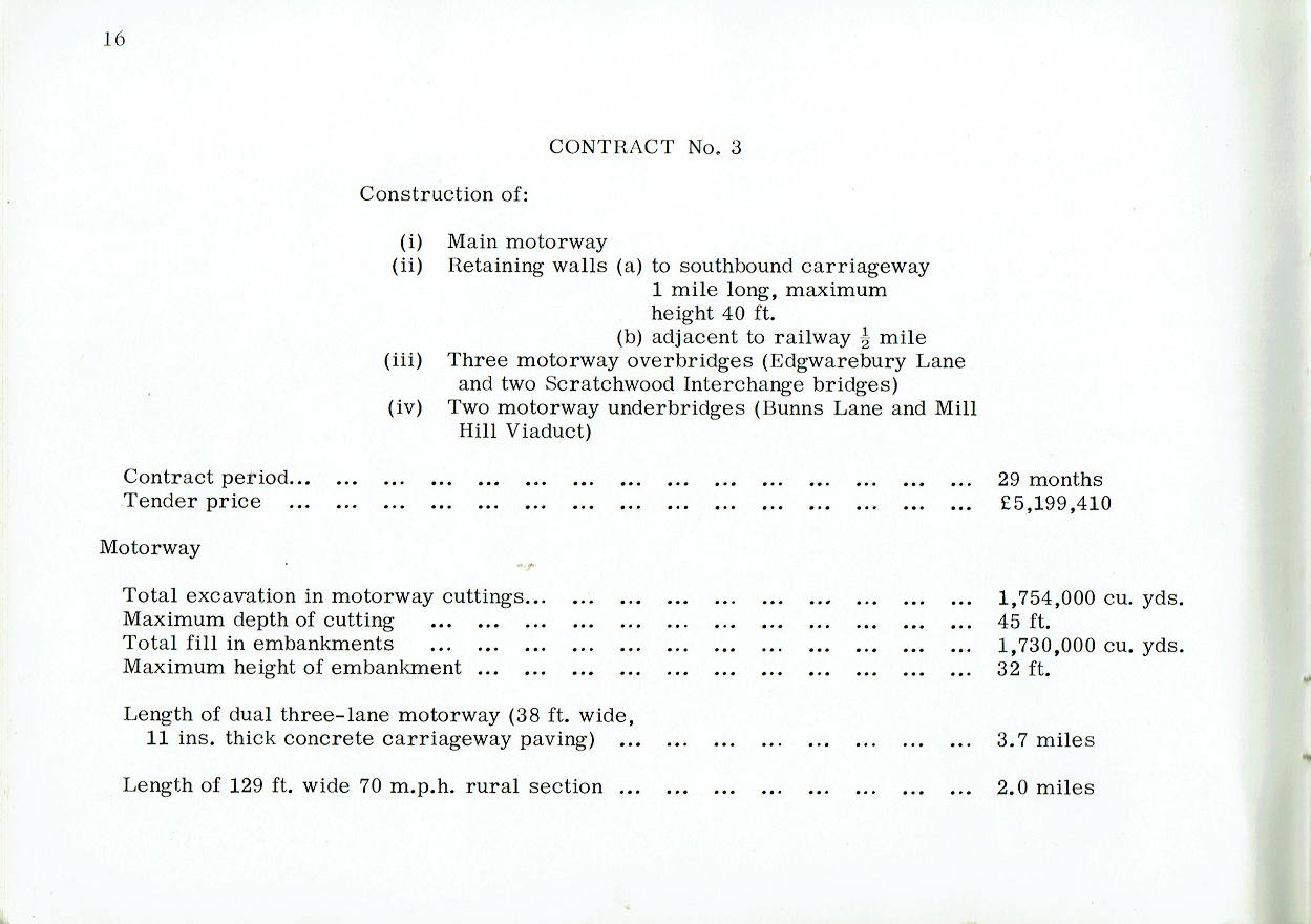
CONTRACT No. 3
Construction of:
- Main motorway
- Retaining walls
- to southbound carriageway 1 mile long, maximum height 40 ft.
- adjacent to railway ½ mile
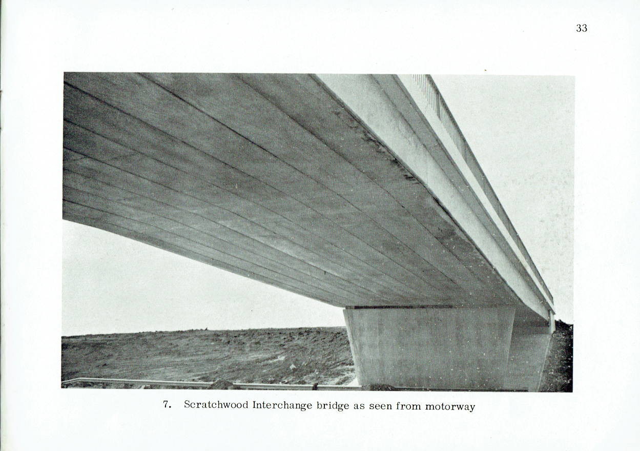
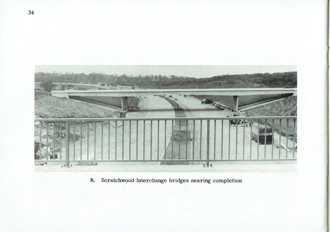
- Three motorway overbridges (Edgwarebury Lane and two Scratchwood Interchange bridges)
- Two motorway underbridges (Buns Lane and Mill Hill Viaduct)
| Contract period | 29 months | |
| Tender price | £5,199,410 | |
| Motorway | Total excavation in motorway cuttings | 1,754,000 cu. yds. |
| Maximum depth of cutting | 45 ft. | |
| Total fill in embankments | 1,730,000 cu. yds. | |
| Maximum height of embankment | 32 ft. | |
| Length of dual three-lane motorway (38 ft. wide, 11 ins. thick concrete carriageway paving) | 3.7 miles | |
| Length of 129 ft. wide 70 m.p.h. rural section | 2.0 miles | |
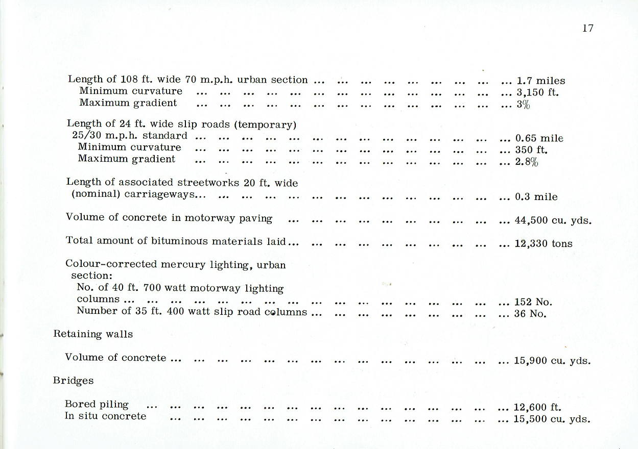
| Length of 108 ft. wide 70 m.p.h. urban section | 1.7 miles | |
| Minimum curvature of urban section | 3,150 ft. | |
| Maximum gradient of urban section | 3% | |
| Length of 24 ft. wide slip roads (temporary) 25/30 m.ph. standard | 0.65 mile | |
| Minimum curvature of slip roads | 350 ft. | |
| Maximum gradient of slip roads | 2.8% | |
| Length of associated streetworks 20 ft. wide (nominal) carriageways | 0.3 mile | |
| Volume of concrete in motorway paving | 44,500 cu. yds. | |
| Total amount of bituminous materials laid | 12,330 tons | |
| Colour-corrected mercury lighting, urban section: | ||
| No. of 40 ft. 700 watt motorway lighting columns | 152 No. | |
| Number of 35 ft. 400 watt slip road columns | 36 No. | |
| Retaining walls | Volume of concrete | 15,900 cu. yds. |
| Bridges | Bored piling | 12,600 ft. |
| In situ concrete | 15,500 cu. yds. | |
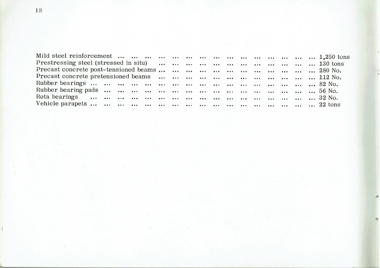
| Mild steel reinforcement | 1,250 tons | |
| Prestressing steel (stressed in situ) | 130 tons | |
| Precast concrete post-tensioned beams | 280 No. | |
| Precast concrete pretensioned beams | 112 No. | |
| Rubber bearings | 82 No. | |
| Rubber bearing pads | 56 No. | |
| Rota bearings | 32 No. | |
| Vehicle parapets | 22 tons | |
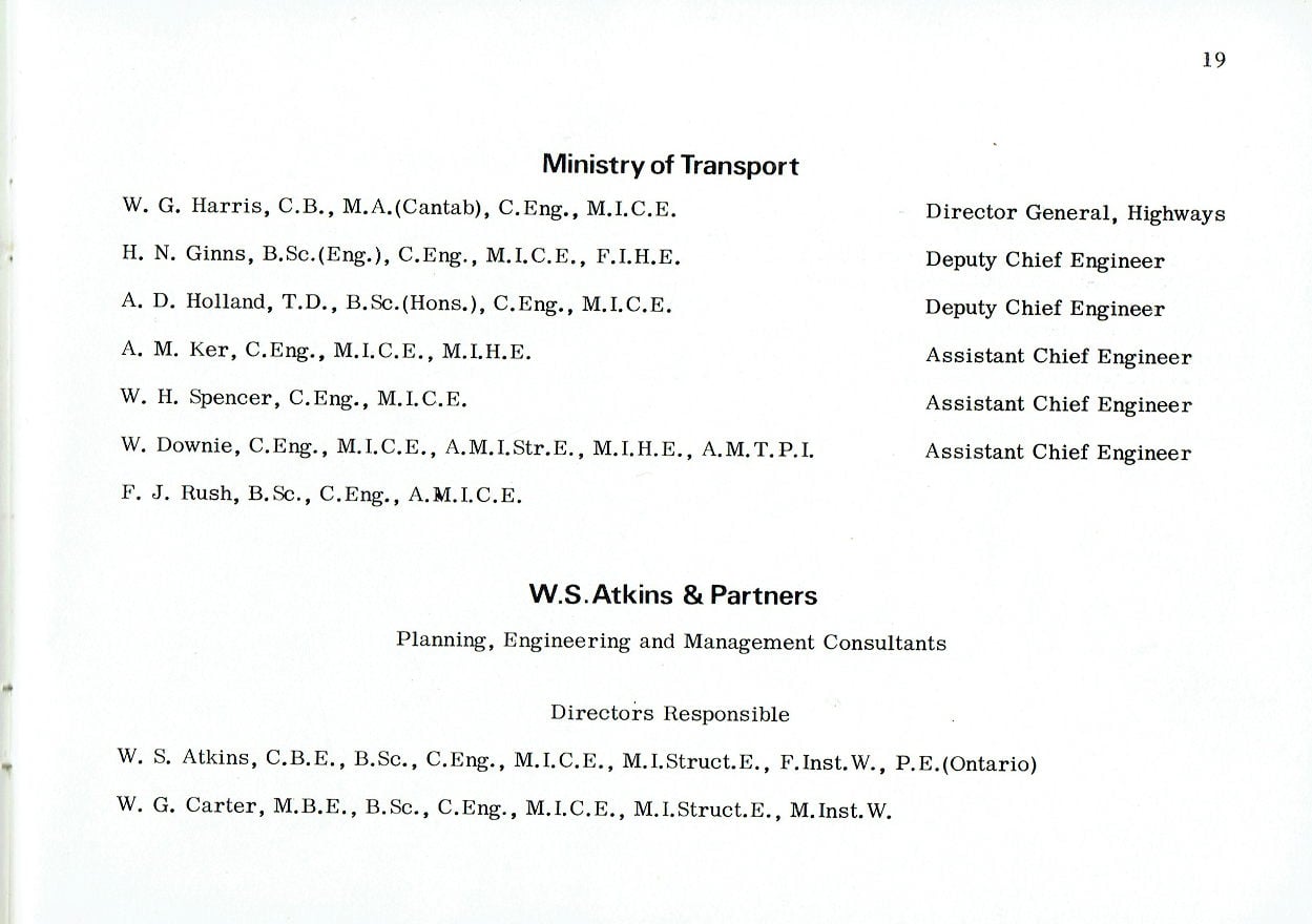
Ministry of Transport
| W. G. Harris, C.B., M.A. (Cantab), C. Eng., M.I.C.E. | Director General, Highways |
| H. N. Ginns, B.Sc. (Eng.), C. Eng., M.I.C.E., F.I.H.E. | Deputy Chief Engineer |
| A. D. Holland, T.D., B.Sc. (Hons.), C. Eng., M.I.C.E. | Deputy Chief Engineer |
| A. M. Ker, C. Eng., M.I.C.E., M.I.H.E. | Assistant Chief Engineer |
| W. H. Spencer, C.Eng., M.I.C.E. | Assistant Chief Engineer |
| W. Downie, C.Eng., M.I.C.E., A.M.I.Str. E., M.I.H.E., A.M.T.P.I. | Assistant Chief Engineer |
| F. J. Rush, B. Sc., C. Eng., A.M.I.C.E. |
W.S. Atkins & Partners
Planning, Engineering and Management Consultants
Directors Responsible
W. S. Atkins, C.B. E., B.Sc., C.Eng., M.I.C.E., M.I.Struct. E., F. Inst. W., P.E. (Ontario)
W. G. Carter, M. B.E., B. Sc., C.Eng., M. I. C. E., M. I.Struct. E., M. Inst. W.
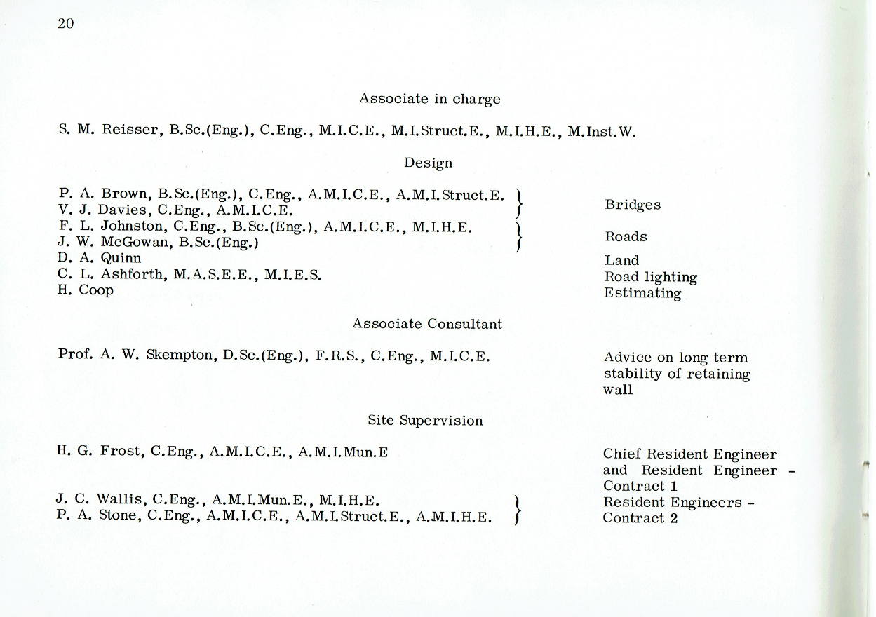
Associate in charge
S. M. Reisser, B.Sc. (Eng.), C. Eng., M.I.C. E., M. I. Struct. E., M.I. H. E., M. Inst. W.
Design
| P. A. Brown, B.Sc. (Eng.), C.Eng., A.M.I.C.E., A.M.I.Struct. | Bridges |
| V. J. Davies, C.Eng., A.M.I.C.E. | |
| F. L. Johnston, C. Eng., B.Sc.(Eng.), A.M.I.C.E., M.I.H.E. | Roads |
| J. W. McGowan, B.Sc. (Eng.) | |
| D. A. Quinn | Land |
| C. L. Ashforth, M.A.S.E.E., M.I.E.S. | Road lighting |
| H. Coop | Estimating |
Associate Consultant
| Prof. A. W. Skempton, D.Sc. (Eng.), F.R.S., C.Eng., M.I.C.E. | Advice on long term stability of retaining wall |
Site Supervision
| H. G. Frost, C. Eng., A.M.I.C.E., A.M.I. Mun. E. | Chief Resident Engineer and Resident Engineer, Contract 1 |
| J. C. Wallis, C. Eng., A.M.I. Mun. E., M.I.H.E. | Resident Engineers, Contract 2 |
| P. A. Stone, C.Eng., A.M.I.C.E., A.M.I. Struct. E., A.M.I.H.E. | |
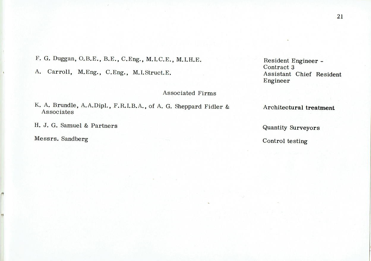
| F. G. Duggan, O.B.E., B.E., C. Eng., M.I.C.E., M.I.H.E. | Resident Engineer, Contract 3 |
| A. Carroll, M.Eng., C.Eng., M.I.Struct. E. | Assistant Chief Resident Engineer |
Associated Firms
| K. A. Brundle, A. A. Dipl., F.R.I. B.A., of A. G. Sheppard Fidler & Associates | Architectural treatment |
| H. J. G. Samuel & Partners | Quantity Surveyors |
| Messrs. Sandberg | Control testing |
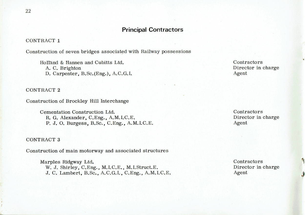
Principal Contractors
CONTRACT 1
Construction of seven bridges associated with Railway possessions
| Holland & Hannen and Cubitts Ltd. | Contractors |
| A. C. Brighton | Director in charge |
| D. Carpenter, B.Sc. (Eng.), A.C.G.I. | Agent |
CONTRACT 2
Construction of Brockley Hill Interchange
| Cementation Construction Ltd. | Contractors |
| R. G. Alexander, C.Eng., A.M.I.C.E. | Director in charge |
| P. J. O. Burgess, B.Sc., C. Eng., A.M.I.C.E. | Agent |
CONTRACT 3
Construction of main motorway and associated structures
| Marples Ridgway Ltd. | Contractors |
| W. J. Shirley, C.Eng., M.I.C.E., M.I.Struct. E. | Director in charge |
| J. C. Lambert, B.Sc., A.C.G.I., C. Eng., A.M.I.C.E. | Agent |
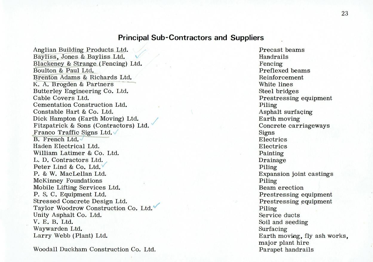
Principal Sub-Contractors and Suppliers
| Anglian Building Products Ltd. | Precast beams |
| Bayliss, Jones & Bayliss Ltd. | Handrails |
| Blackeney & Strange (Fencing) Ltd. | Fencing |
| Boulton & Paul Ltd. | Preflexed beams |
| Brenton Adams & Richards Ltd. | Reinforcement |
| K. A. Brogden & Partners | White lines |
| Butterley Engineering Co. Ltd. | Steel bridges |
| Cable Covers Ltd. | Prestressing equipment |
| Cementation Construction Ltd. | Piling |
| Constable Hart & Co. Ltd. | Asphalt surfacing |
| Dick Hampton (Earth Moving) Ltd. | Earth moving |
| Fitzpatrick & Sons (Contractors) Ltd. | Concrete carriageways |
| Franco Traffic Signs Ltd. | Signs |
| B. French Ltd. | Electrics |
| Haden Electrical Ltd. | Electrics |
| William Latimer & Co. Ltd. | Painting |
| L. D. Contractors Ltd. | Drainage |
| Peter Lind & Co. Ltd. | Piling |
| P. & W. MacLellan Ltd. | Expansion joint castings |
| McKinney Foundations | Piling |
| Mobile Lifting Services Ltd. | Beam erection |
| P. S. C. Equipment Ltd. | Prestressing equipment |
| Stressed Concrete Design Ltd. | Prestressing equipment |
| Taylor Woodrow Construction Co. Ltd. | Piling |
| Unity Asphalt Co. Ltd. | Service ducts |
| V. E. B. Ltd. | Soil and seeding |
| Waywarden Ltd. | Surfacing |
| Larry Webb (Plant) Ltd. | Earth moving, fly ash works, major plant hire |
| Woodall Duckham Construction Co. Ltd. | Parapet handrails |
