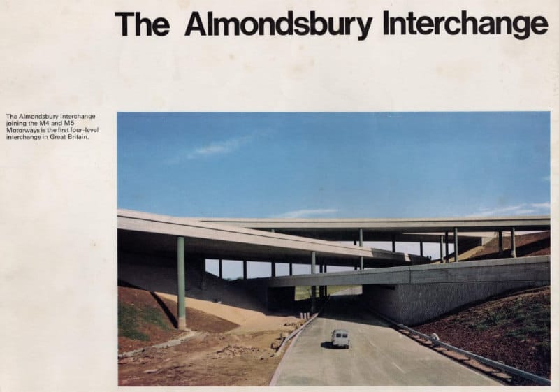
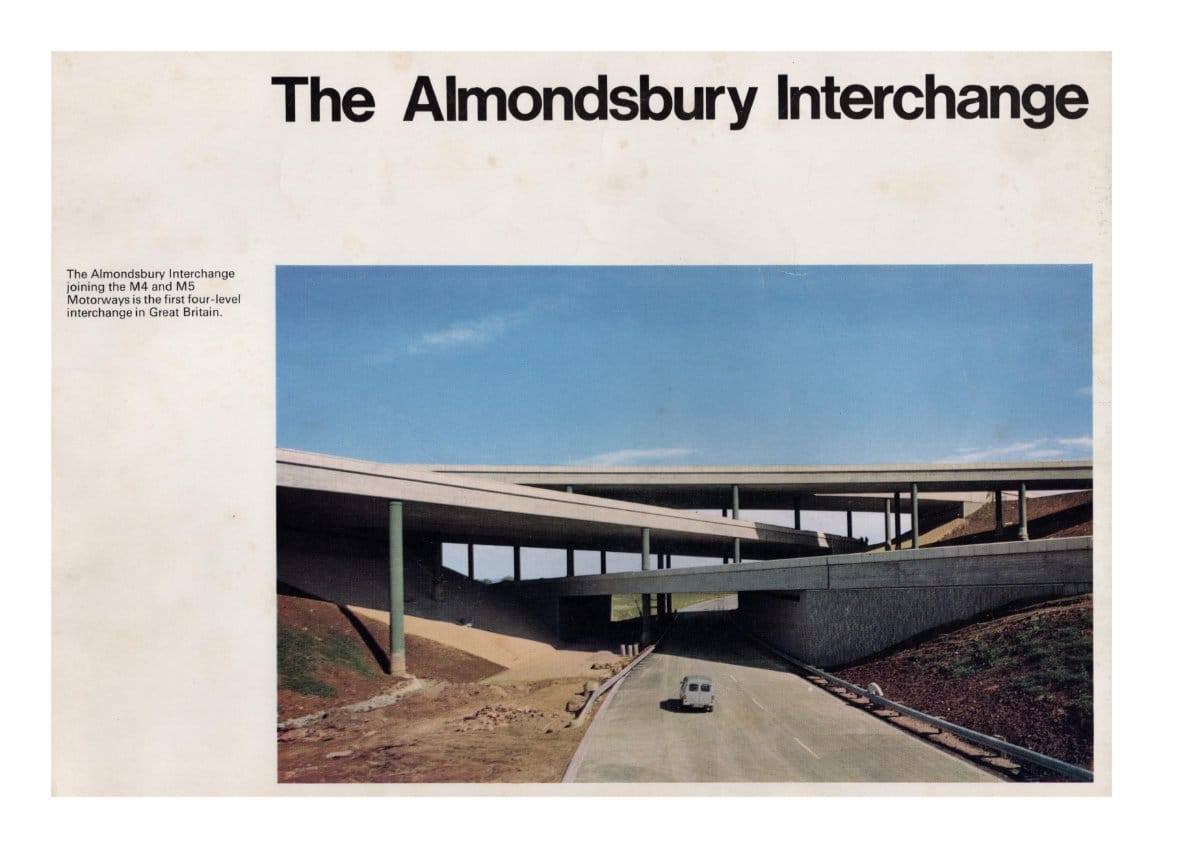
There are just three four-level stack interchanges in the UK, a type of junction where sliproads connecting two motorways are piled up four levels high. The first of them, opened to traffic in 1966, was Almondsbury Interchange, connecting the M4 and M5 near Bristol.
It would be hard to overstate just what a pioneering achievement this was considered to be, at the time it was opened, or just how remarkable and new this kind of junction was. The UK had seen nothing like it before; it was the first time two motorways had crossed each other and the first time a structure of such complexity had been built. No wonder its designers though that the junction itself - not the roads it connected, which were built as part of the same contract - was worthy of a commemorative booklet of its very own.
This booklet was published when the interchange first opened to traffic, at which time it wasn't yet complete and only made connections between three approaches. It linked the M4 near Bristol to a short length of M5 heading southwards towards the Avon. The M5 to the north was still in planning, so while the junction was designed to allow its connection, it didn't yet exist. The rest of the interchange was completed, using earthworks and structures already in place, in 1971.
Page 1
Page 2
Page 3
Page 4
Page 5
Page 6
Page 7
Page 8
Page 9
Page 10
Page 11
Page 12
Page 13
Page 14
Page 15
Page 16
Page 17
Page 18

Page 19
Page 20
Page 21
Page 22
Page 23

Page 24
Inside front cover
- Built for the Ministry of Transport.
- Consulting Engineers: Freeman, Fox and Partners.
- Associated with Robert F. Earley.
- Architect: R. E. Slater ARIBA.
- Main Contractor: Richard Costain Civil Engineening Limited.
- Photography by courtesy of Freeman Fox and Partners, Richard Costain Limited, Hunting Surveys Limited, Krisson Design Group.
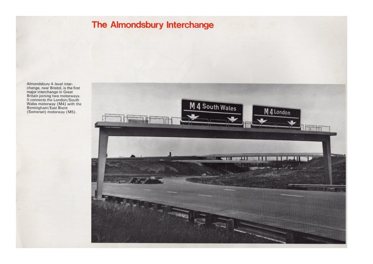
The Almondsbury Interchange
Almondsbury 4-level interchange, near Bristol, is the first major interchange in Great Britain joining two motorways. It connects the London South Wales motorway (M4) with the Birmingham/East Brent (Somerset) motorway (M5).
Introduction
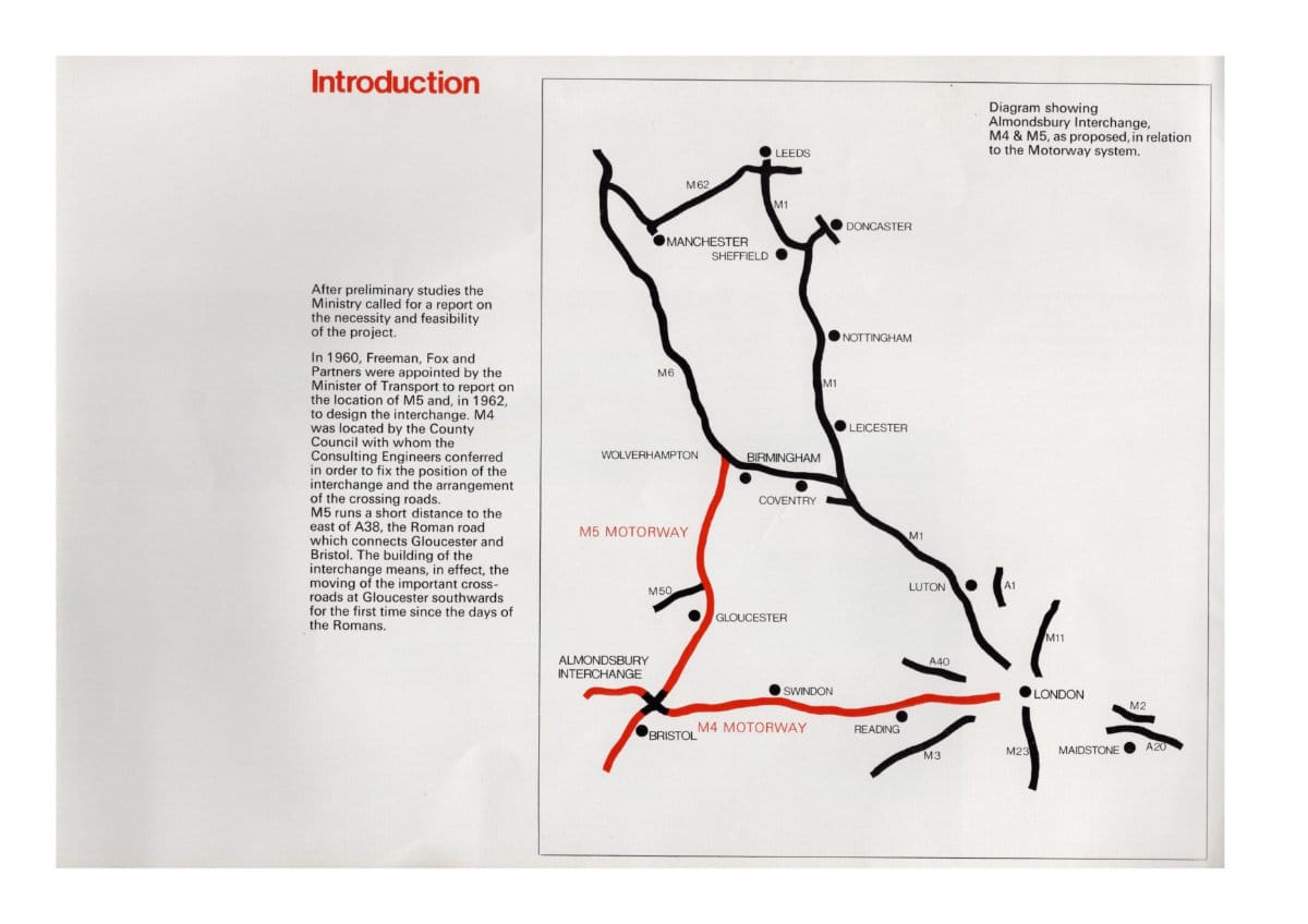
After preliminary studies the Ministry called for a report on the necessity and feasibility of the project. In 1960, Freeman, Fox and Partners were appointed by the Minister of Transport to report on the location of M5 and, in 1962, to design the interchange. M4 was located by the County Council with whom the Consulting Engineers conferred in order to fix the position of the interchange and the arrangement of the crossing roads.
M5 runs a short distance to the east of A38, the Roman road which connects Gloucester and Bristol. The building of the interchange means, in effect, the moving of the important crossroads at Gloucester southwards for the first time since the days of the Romans.
Planning and Surveys
The detailed large scale ground survey was carried out by Messrs J. A. Story and Partners, who established pegs on the site from which the interchange was ultimately set out by the contractor.
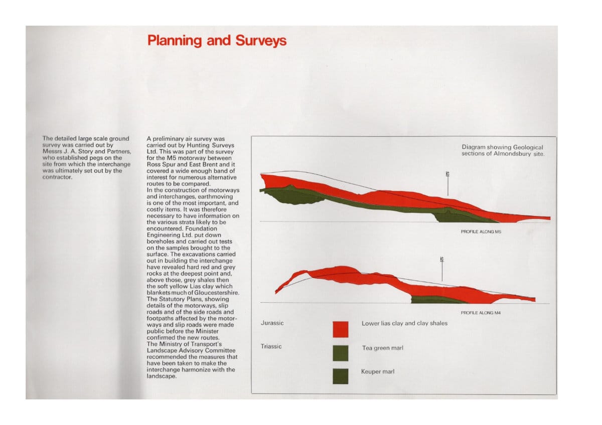
A preliminary air survey was carried out by Hunting Surveys Ltd. This was part of the survey for the M5 motorway between Ross Sour and East Brent and it covered a wide enough band of interest for numerous alternative routes to be compared. In the construction of motorways and interchanges, earthmoving is one of the most important and costly items. It was therefore necessary to have information on the various strata likely to be encountered. Foundation Engineering Ltd. put down boreholes and carried out tests on the samples brought to the surtace. The excavations carried out in building the interchange have revealed hard red and grey rocks at the deepest point and above those, grey shales then the soft yellow Lias clay which blankets much of Gloucestershire. The Statutory Plans, showing details of the motorways, slip roads and of the side roads and footpaths affected by the motorways and slip roads were made public before the Minister confirmed the new routes. The Ministry of Transport's Landscape Advisory Committee recommended the measures that have been taken to make the interchange harmonize with the landscape.
Traffic and Services
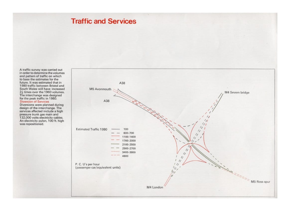
A traffic survey was carried out in order to determine the volumes and pattern of traffic on which to base the estimates for the future. It was estimated that in 1980 traffic between Bristol and South Wales will have increased 2½ times over the 1960 volumes. The interchange was designed for the peak traffic in 1980.
Diversion of Services
Diversions were planned during design of the interchange. The services affected include a high pressure trunk gas main and 132,000 volts electricity cables. An electriciy pylon, 100 ft high, was repostioned.
Acquisition of Land
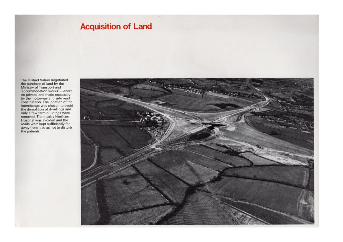
The District Valuer negotiated the purchase of land by the Ministry of Transport and 'accommodation works' - works on private land made necessary by the motorway and side road construction. The location of the interchange was chosen to avoid the demolition of dwellings and only a few farm buildings were removed. The nearby Hortham Hospital was avoided and the roads were kept sufficiently far away from it so as not to disturb the patients.
Design of the Interchange
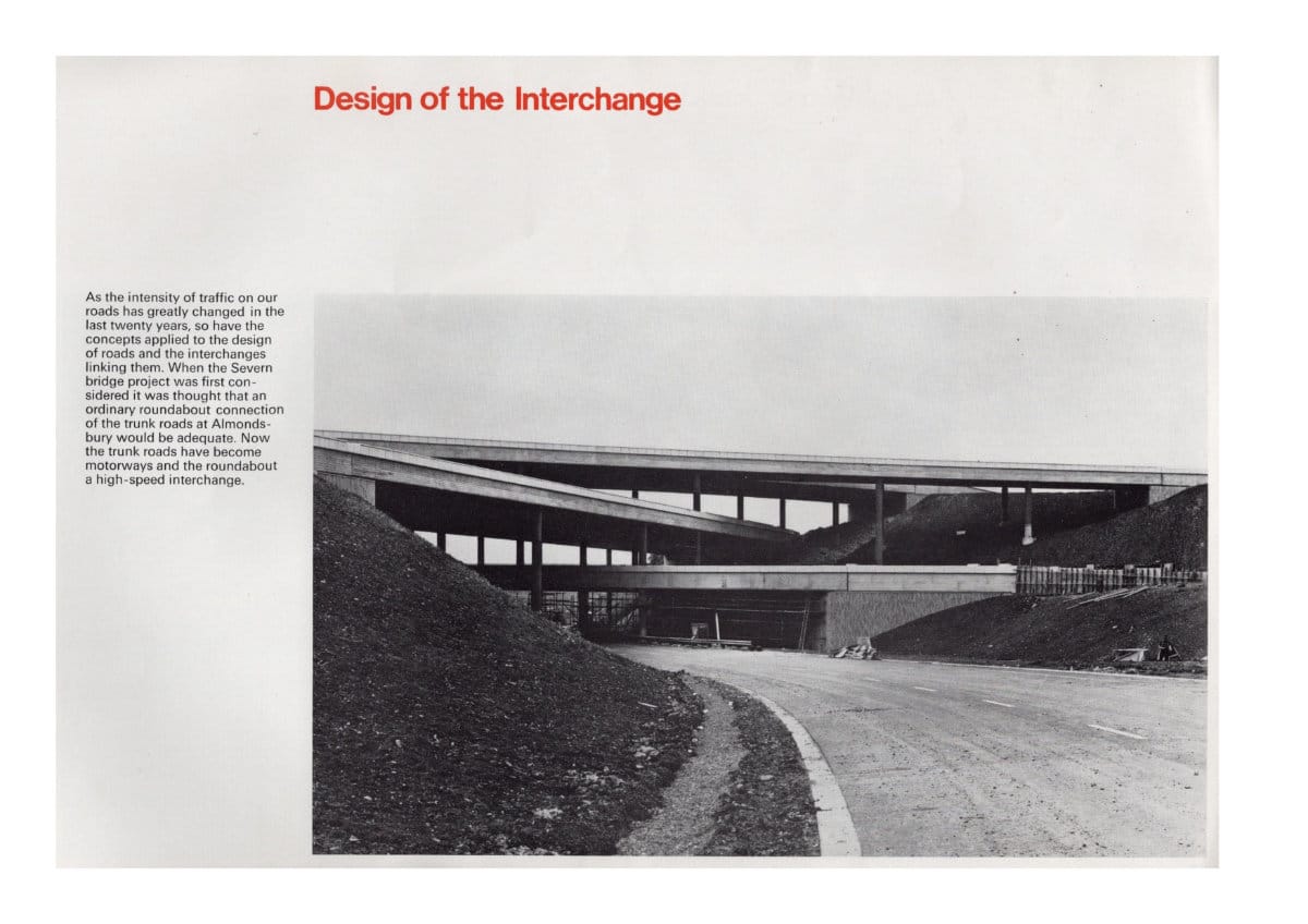
As the intensity of traffic on our roads has greatly changed in the last twenty years, so have the concepts applied to the design of roads and the interchanges linking them. When the Severn Bridge prolect was first considered it was thought that an ordinary roundabout connection of the trunk roads at Almondsbury would be adequate. Now the trunk roads have become motorways and the roundabout a high-speed interchange.
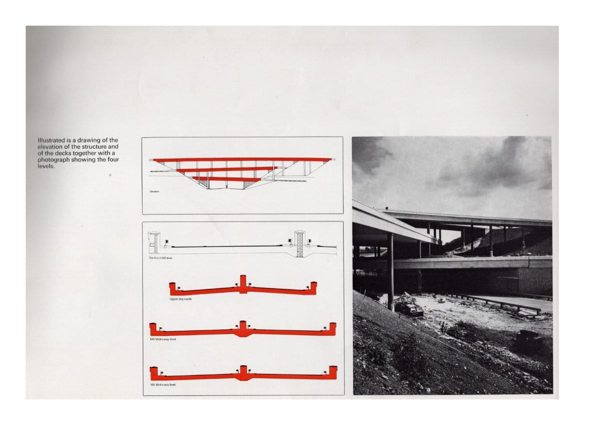
Illustrated is a drawing of the elevation of the structure and of the decks together with a photograph showing the four levels.
Alternatives considered
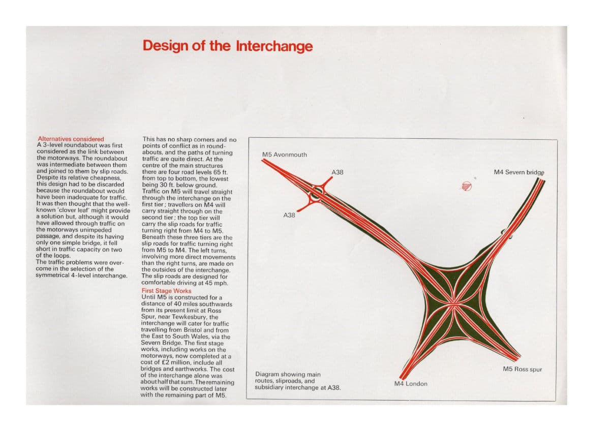
A 3-level roundabout was first considered as the link between the motorways. The roundabout was intermediate between then and joined to them by slip roads. Despite its relative cheapness, this design had to be discarded because the roundabout would have been inadequate for traffic. It was then thought that the well known 'clover leaf' might provide a solution but, although it would have allowed through traffic on the motorways unimpeded passage, and despite its having one simple bridge, it fell short in traffic capacity on two of the loops.
The traffic problems were overcome in the selection of the symmetrical 4-level interchange.
This has no sharp corners and no points of conflict as in roundabouts, and the paths of turning traffic are quite direct. At the centre of the main structures there are four road levels 65 ft. from top to bottom, the lowest being 30 ft. below ground. Traffic on M5 will travel straight through the interchange on the first tier; travellers on M4 will carry straight through on the second tier; the top tier will carry the sliproads for traffic turning right from M4 to M5. Beneath these three tiers are the slip roads for traffic turning right from M5 to M4. The left turns, involving more direct movements than the right turns, are made on the outsides of the interchange. The slip roads are designed for comfortable driving at 45 mph.
First Stage Works
Until M5 is constructed for a distance of 40 miles southwards from its present limit at Ross Spur, near Tewkesbury, the interchange will cater for traffic travelling from Bristol and from the East to South Wales, via the Severn Bridge. The first stage works, including works on the motorways, now completed at a cost of £2 million, include all bridges and earthworks. The cost of the interchange alone was about half that sum. The remaining works will be constructed later with the remaining part of M5.
Subsidiary interchange
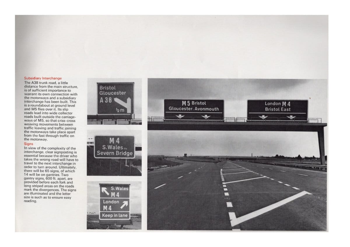
The A38 trunk road, a little distance from the main structure, is of sufficient importance to warrant its own connection with the motorways and a subsidiary interchange has been built. This is a roundabout at ground level and M5 flies over it. Its slip roads lead into wide collector roads built outside the carriageways of M5, so that criss-cross weaving movements between traffic leaving and traffic joining the motorways take place apart from the fast through traffic on the motorway.
Signs
In view of the complexity of the interchange, clear signposting is essential because the driver who takes the wrong road wil have to travel to the next interchange in order to turn around. Ultimately. there will be 65 signs. of which 14 will be on gantries. Two gantry signs, 600 ft. apart, are provided before each fork and long striped areas on the roads mark the divergences. The signs are illuminated and the letter size is such as to ensure easy reading.
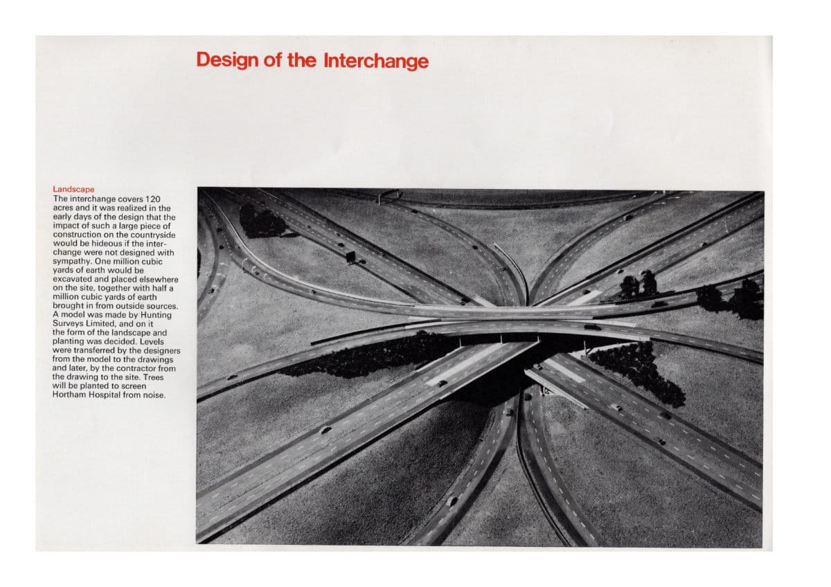
Landscape
The interchange covers 120 acres and it was realized in the early days of the design that the impact of such a large piece of construction on the countryside would be hideous if the interchange were not designed with sympathy. One million cubic yards of earth would be excavated and placed elsewhere on the site, together with half a million cubic yards of earth brought in from outside sources. A model was made by Hunting Surveys Limited, and on it the form of the landscape and planting was decided. Levels were transferred from the model to the drawings and later, by the contractor from the drawing to the site. Trees will be planted to screen Hortham Hospital from noise.
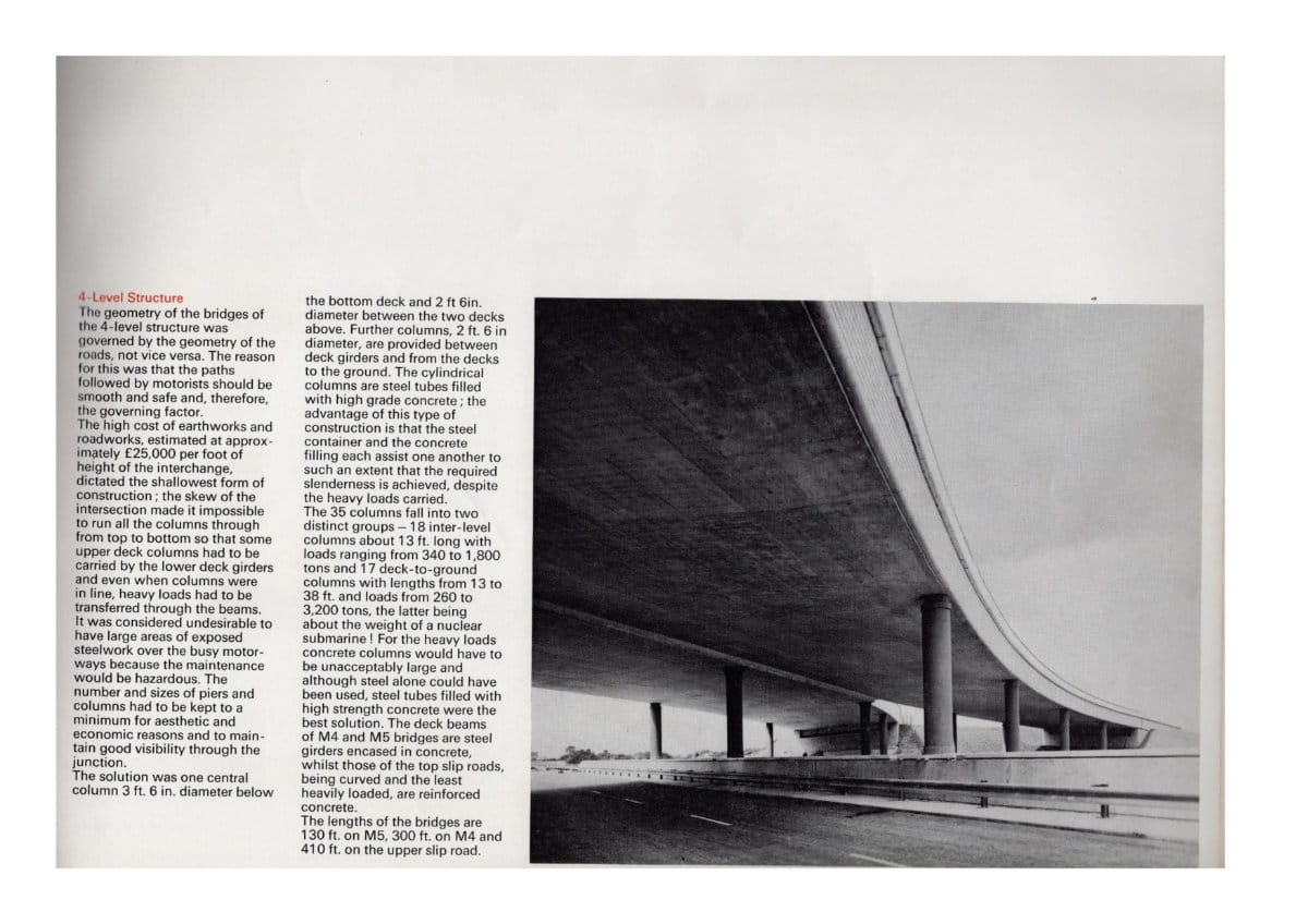
4-Level Structure
The geometry of the bridges of the 4-level structure was governed by the geometry of the roads, not vice versa. The reason for this was that the paths followed by motorists should be smooth and safe and, therefore, the governing factor.
The high cost of earthworks and road works, estimated at approximately £25,000 per foot of height of the interchange, dictated the shallowest form of construction; the skew of the intersection made it impossible to run all the columns through from top to bottom so that some upper deck columns had to be carried by the lower deck girders and even when columns were in line, heavy loads had to be transferred through the beams. It was considered undesirable to have large areas of exposed steeIwork over the busy motorways because the maintenance would be hazardous. The number and sizes of piers and columns had to be kept to a minimum for aesthetic and economic reasons and to maintain good visibility through the junction.
The solution was one central column 3 ft. 6 in. diameter below the bottom deck and 2 ft 6in. diameter between the two decks above. Further columns, 2 ft. 6 in. diameter, are provided between deck girders and from the decks to the ground. The cylindrical columns are steel tubes filled with high grade concrete; the advantage of this type of construction is that the steel container and the concrete filling each assist one another to such an extent that the required stenderness is achieved, despite the heavy loads carried.
The 35 columns fall into two distinct groups - 18 inter-level columns about 13 ft. long with loads ranging from 340 to 1,800 tons and 17 deck-to-ground columns with lengths from 13 to 38 ft. and loads from 260 to 3,200 tons, the latter being about the weight of a nuclear submarine! For the heavy loads concrete columns would have to be unacceptably large and although steel alone could have been used, steel tubes filled with high strength concrete were the best solution. The deck beams of M4 and M5 bridges are steel girders encased in concrete, whilst those of the top slip roads, being curved and the least heavily loaded, are reinforced concrete.
The lengths of the bridges are 130 ft. on M5, 300 ft. on M4 and 410 ft. on the upper slip road.
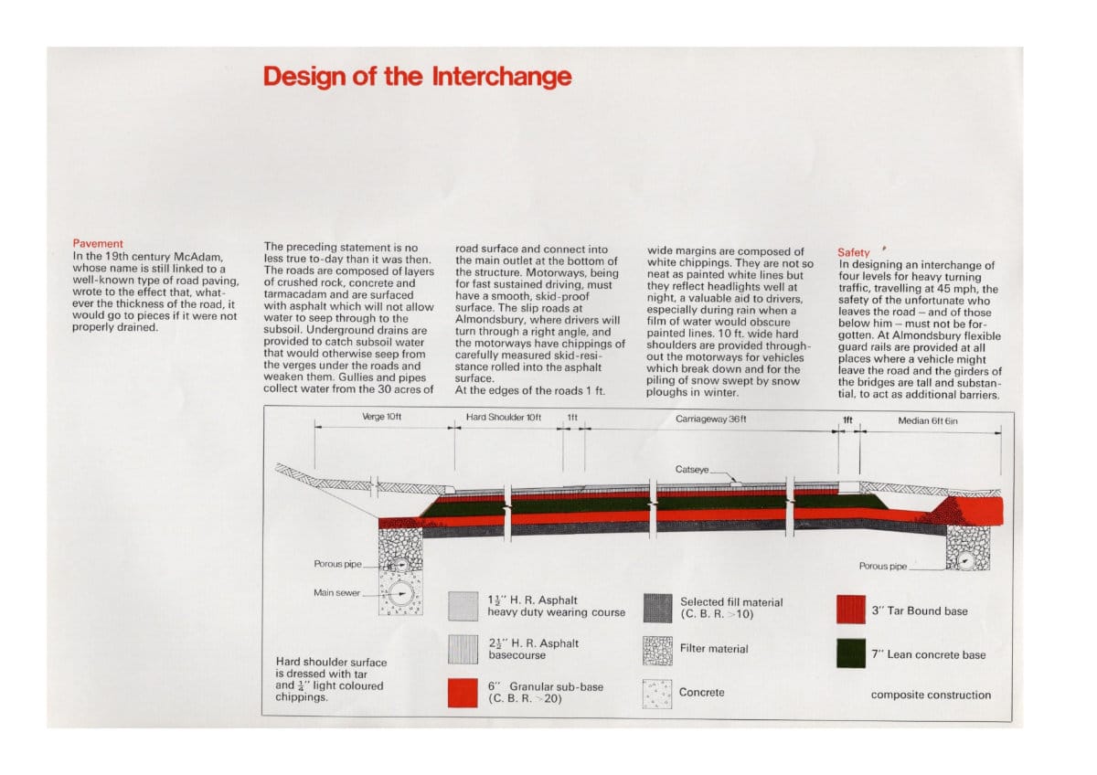
Pavement
In the 19th century McAdam, whose name is still linked to a well-known type of road paving, wrote to the effect that, whatever the thickness of the road, it would go to pieces if it were not properly drained.
The preceding statement is no less true to-day than it was then. The roads are composed of layers of crushed rock, concrete and tarmacadam and are surfaced with asphalt which will not allow water to seep through to the subsoil. Underground drains are provided to catch subsoil water that would otherwise seep from the verges under the roads and weaken them. Gullies and pipes collect water from the 30 acres of road surface and connect into the main outlet at the bottom of the structure. Motorways, being for fast sustained driving, must have a smooth, skid-proof surface. The slip roads at Almondsbury, where drivers will turn through a right angle, and the motorways have chippings of carefully measured skid-resistance rolled into the asphalt surface.
At the edges of the roads 1 ft. wide margins are composed of white chippings. They are not so neat as painted white lines but they reflect headlights well at night, a valuable aid to drivers, especially during rain when a film of water would obscure painted lines. 10 ft. wide hard shouiders are provided throughout the motorways for vehicles which break down and for the piling of snow swept by snow ploughs in the winter.
Safety
In designing an interchange of four levels for heavy turning traffic, travelling at 45 mph, the safety of the unfortunate who leaves the road - and of those below him - must not be forgotten. At Almondsbury flexible guard rails are provided at all places where a vehicle might leave the road and the girders of the bridges are tall and substantial, to act as additional barriers.
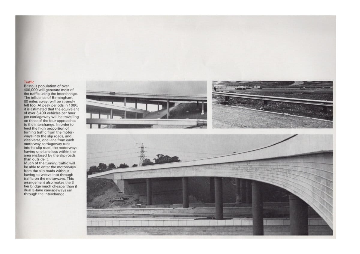
Traffic
Bristol's population of over 400,000 will generate most of the traffic using the interchange. The influence of Birmingham, 80 miles away, will be strongly felt too. At peak periods in 1980, it is estimated that the equivalent of over 3,400 vehicles per hour per carriageway will be travelling on three of the four approaches to the interchange. In order to feed the high proportion of turning traffic from the motorways into the slip roads, and vice versa, one lane from each carriageway runs into its slip road, the motorways having one lane less within the area enclosed by the slip roads than outside it.
Much of the turning traffic will be able to enter the motorways from the slip roads without having to weave into through traffic on the motorways. This arrangement also makes the 3 tier bridge much cheaper than if dual 3-lane carriageways ran through the interchange.
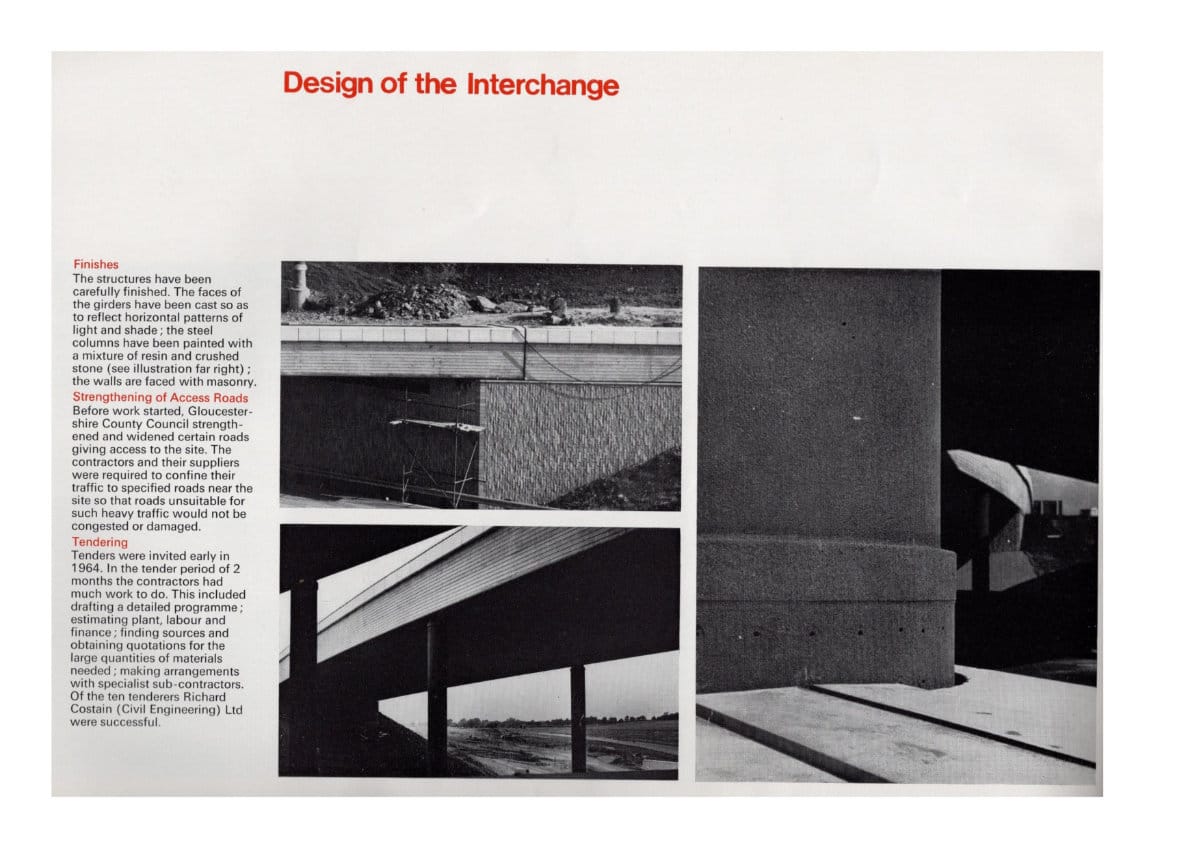
Finishes
The structures have been carefully finished. The faces of the girders have been cast so as to reflect horizontal patterns of light and shade; the steel columns have been painted with a mixture of resin and crushed stone (see illustration far right); the walls are faced with masonry.
Strengthening of Access Roads
Before work started, Gloucestershire County Council strengthened and widened certain roads giving access to the site. The contractors and their suppliers were required to confine their traffic to specified roads near the site so that roads unsuitable for such heavy traffic would not be congested or damaged.
Tendering
Tenders were invited early in 1964. In the tender period of 2 months the contractors had much work to do. This included drafting a detailed programme; estimating plant, labour and finance; finding sources and obtaining quotations for the large quantities of materials needed; making arrangements with specialist sub-contractors. Of the ten tenderers Richard Costain (Civil Engineering) Ltd were successful.
Construction
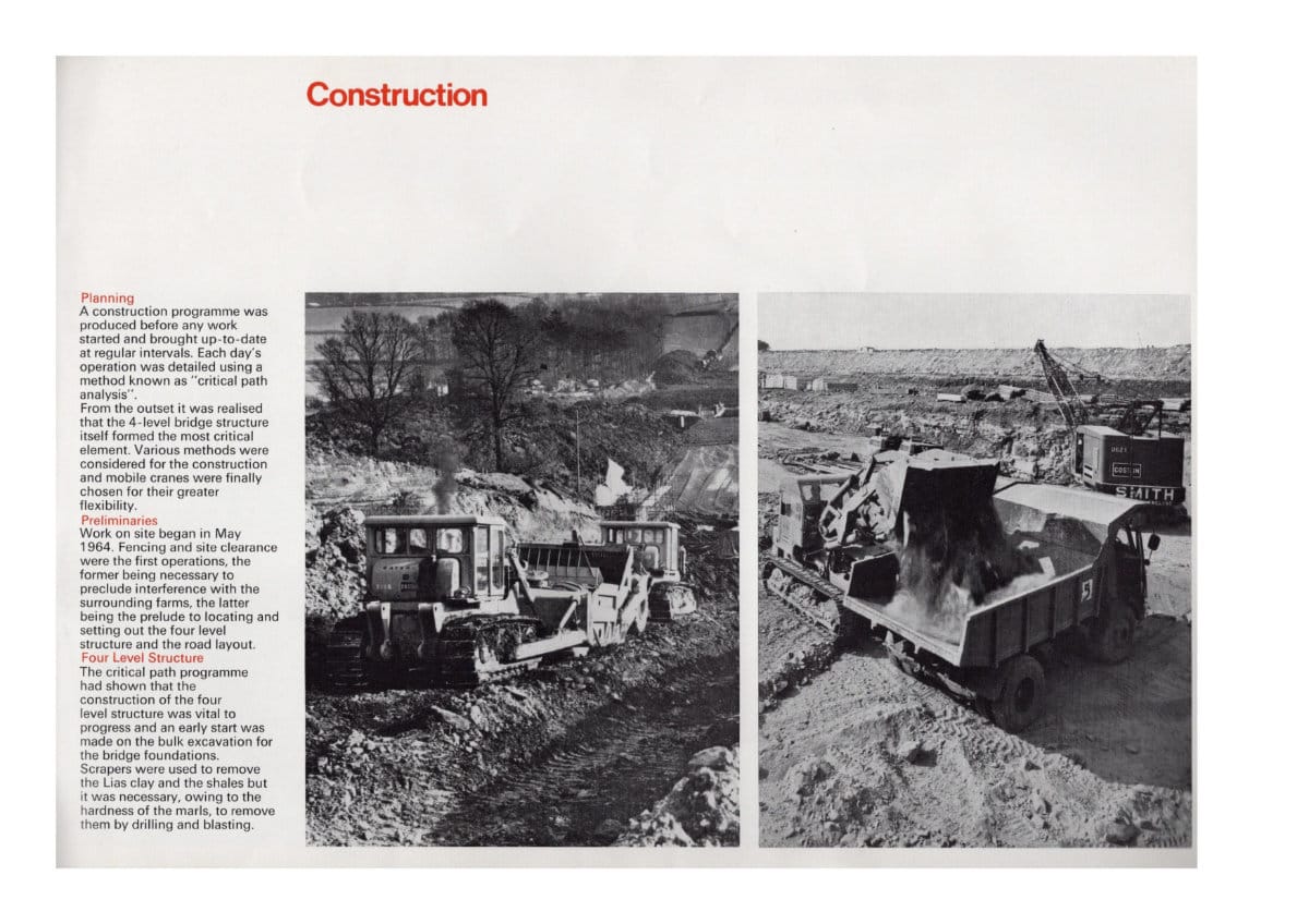
Planning
A construction programme was produced before any work started and brought up-to-date at regular intervals. Each day's operation was detailed using a method known as "critical path analysis".
From the outset it was realised that the 4-level bridge structure itself formed the most critical element. Various methods were considered for the construction and mobile cranes were finally chosen for their greater flexibility.
Preliminaries
Work on site began in May 1964. Fencing and site clearance were the first operations, the former being necessary to preclude interference with the surrounding farms, the latter being the prelude to locating and setting out the four level structure and the road layout.
Four Level Structure
The critical path programme had shown that the construction of the four level structure was vital to progress and an early start was made on the bulk excavation for the bridge foundations.
Scrapers were used to remove the Lias clay and the shales but it was necessary, owing to the hardness of the marls, to remove them by drilling and blasting.
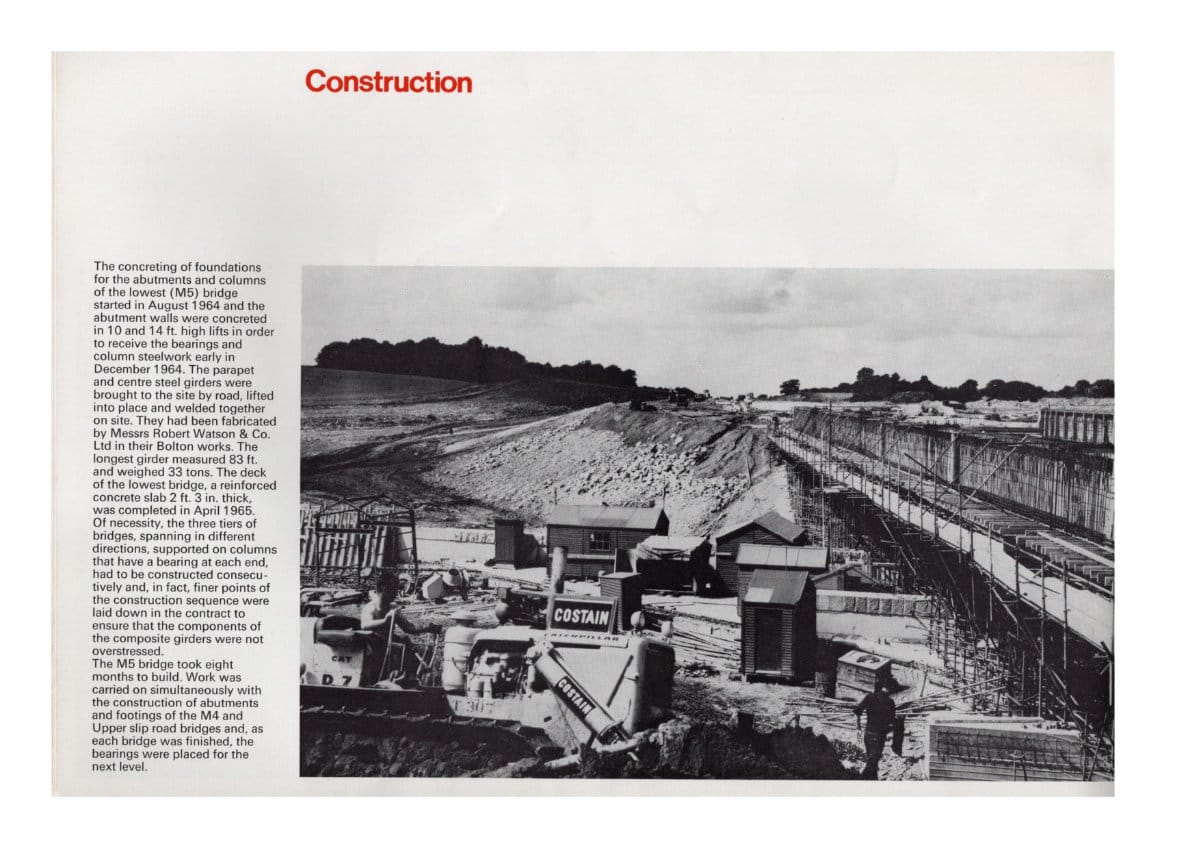
The concreting of foundations for the abutments and columns of the lowest (M5) bridge started in August 1964 and the abutment walls were concreted in 10 and 14 ft. high lifts in order to receive the bearings and column steelwork early in December 1964. The parapet and centre steel girders were brought to the site by road, lifted into place and welded together on site. They had been fabricated by Messrs Robert Watson & Co. Ltd in their Bolton works. The longest girder measured 83 ft. and weighed 33 tons. The deck of the lowest bridge, a reinforced concrete slab 2 ft. 3 in. thick, was completed in April 1965. Of necessity, the three tiers of bridges, spanning in different directions, supported on columns that have a bearing at each end, had to be constructed consecutively and, in fact, finer points of the construction sequence were laid down in the contract to ensure that the components of the composite girders were not overstressed.
The M5 bridge took eight months to build. Work was carried on simultaneously with the construction of abutments and footings of the M4 and Upper slip road bridges and, as each bridge was finished, the bearings were placed for the next level.
The steel tubes, forming the shells of the columns were lifted and guyed and the concrete core poured into place. Then the tubular steel birdcage scaffolding was erected on the M5 bridge to support the timber shuttering of the bridge above. The steel plate girders used in the beams of M4 had to be temporarily supported on steel trestles while they were welded together. All of this had to be done before the actual deck could be concreted. The M4 bridge, involving the placing of 2400 cubic yards of concrete, was finished in September 1965. At this stage work commenced on the construction of the upper slip roads. This involved the placing of 3300 cubic yards of concrete. The last beam section was concreted in April 1966. Pre-mixed concrete was supplied by Hobbs Transmix Ltd. In accordance with modern trends the size of the individual concrete pours was considerable. The deck of M5 bridge,
amounting to 1200 cubic yards (about equivalent to a 10½ yard cube) was concreted in three pours over three days. The largest single pour in the whole structure amounted to 450 cubic yards in a 14 hour shift.
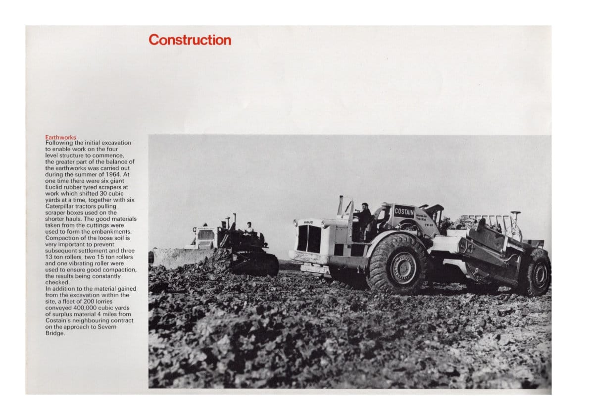
Earthworks
Following the initial excavation to enable work on the four level structure to commence, the greater part of the balance of the earthworks was carried out during the summer of 1964. At one time there were six giant Euclid rubber tyred scrapers at work which shifted 30 cubic yards at a time, together with six Caterpillar tractors pulling scraper boxes used on the shorter hauls. The good materials taken from the cuttings were used to form the embankments. Compaction of the loose soil is very important to prevent subsequent settlement and three 13 ton rollers, two 15 ton rollers and one vibrating roller were used to ensure good compaction, the results being constantly checked.
In addition to the material gained from the excavation within the site, a fleet of 200 lorries conveyed 400,000 cubic yards of surplus material 4 miles trom Costain's neighbouring contract on the approach to Severn Bridge.
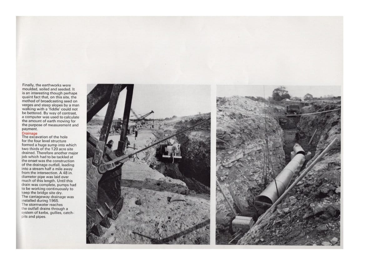
Finally, the earthworks were moulded, soiled and seeded. It is an interesting though perhaps quaint fact that, on this site, the method of broadcasting seed on verges and steep slopes by a man walking with a 'fiddle' could not be bettered. By way of contrast, a computer was used to calculate the amount of earth moving for the purpose of measurement and payment.
Drainage
The excavation of the hole for the four level structure formed a huge sump into which two thirds of the 120 acre site drained. Therefore another major job which had to be tackled at the onset was the construction of the drainage outfall, leading into a stream half a mile away from the intersection. A 48 in. diameter pipe was laid over much of this length. Until this drain was complete, pumps had to be working continuously to keep the bridge site dry.
The carriageway drainage was installed during 1965. The stormwater reaches the outfall drains through a system of kerbs, gullies, catchpits and pipes.
Road Pavement
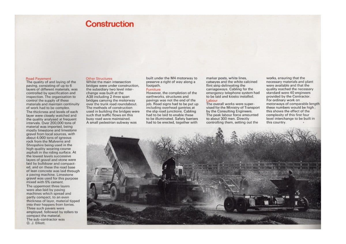
The quality of and laying of the paving, consisting of up to 6 layers of different materials, was controlled by specification and inspection. The organisation to control the supply of these materials and maintain continuity of work had to be complex.
The thickness and levels of each layer were closely watched and the quality analysed at frequent intervals. Over 200,000 tons of material was imported, being mostly limestone and limestone gravel from local sources, with about 4,000 tons of igneous rock from the Malverns and Shropshire being used in the high quality wearing course asphalt in the riding surface. At the lowest levels successive layers of graven and stone were laid by bulldozer and compacted, and on these the road base of lean concrete was laid through a paving machine. Limestone gravel was used for this purpose mixed with 5% cement.
The uppermost three layers were also laid by paving machines which spread and partly compact, to an even thickness of layer, material tipped into their hoppers from lorries. Three such pavers were employed, followed by rollers to compact the material. The sub-contractor was O. J. Elliott.
Other Structures
Whilst the main intersection bridges were under construction, the subsidiary two level interchange was built at the
A38 including 2 three span bridges carrying the motorway over the trunk road roundabout. The methods of construction used in bullding the bridges were such that traffic flows on this busy road were maintained.
A small pedestrian subway was built under the M4 motorway to preserve a right of way along a footpath.
Furniture
However, the completion of the earthworks, structures and pavings was not the end of the job. Road signs had to be put up including overhead gantries at the the slip road junctions. Cabling had to be laid to enable these to be illuminated. Safety barriers had to be erected, together with marker posts, white lines, catseyes and the white calcined flint strip delineating the carriageways. Cabling for the emergency telephone system had to be laid and kiosks installed.
Labour
The overaIl works were well supervised for the Ministry of Transport by the Consulting Engineers. The peak labour force amounted to about 300 men. Directly controlling them, setting out the works, ensuring that the necessary materials and plant were available and that the quality reached the necessary standard were 40 engineers provided by the Contractor.
For ordinary work on motorways of comparable length these numbers would be high; this shows the effect of the complexity of this first four level interchange to be built in this country.
Inside back cover
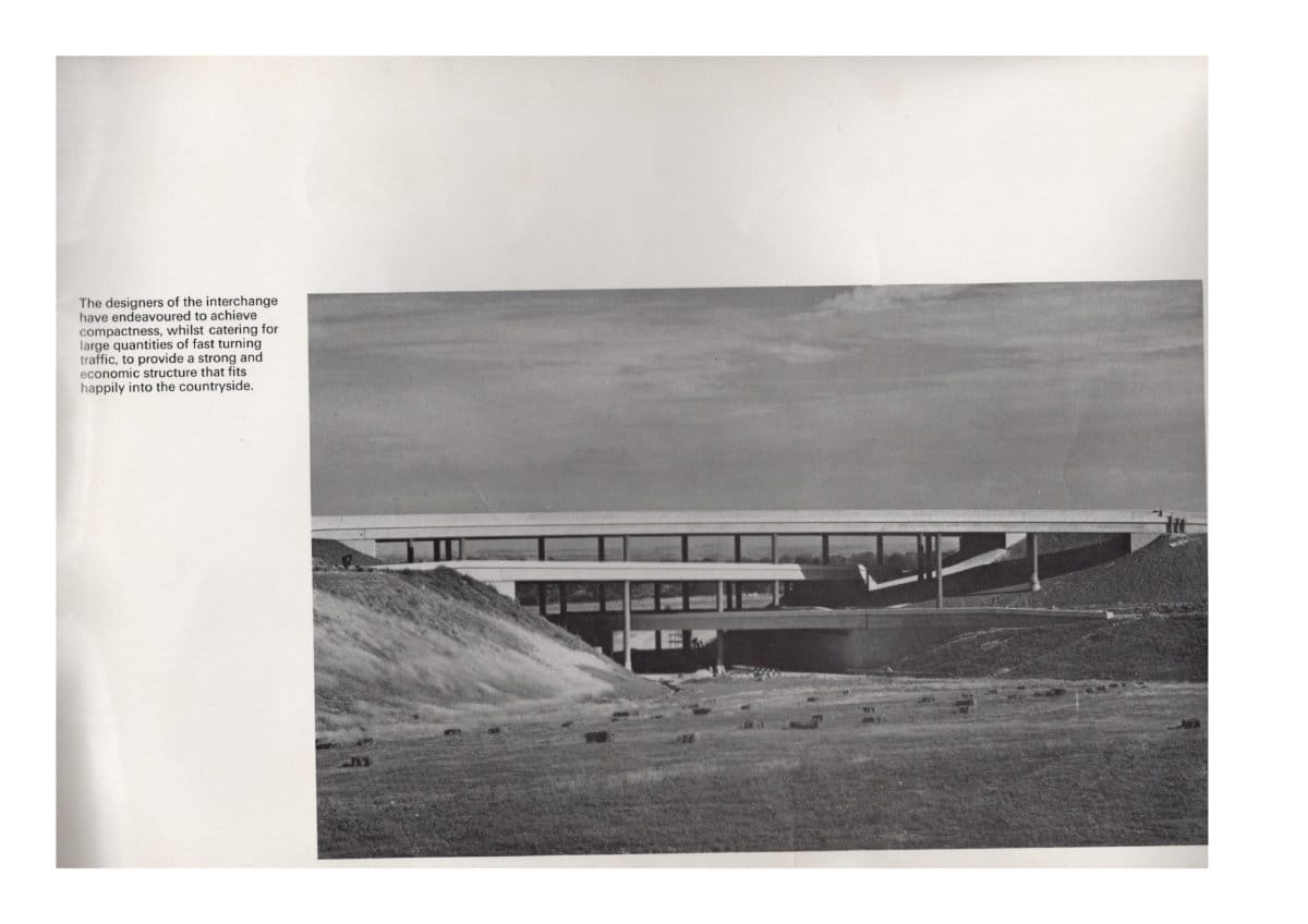
The designers of the interchange have endeavoured to achieve compactness whilst catering to large quantities of fast turning traffic, to provide a strong and economic structure that fits happily into the countryside.
Designed and Produced by Krisson Design Group. Printed in England by Krisson Printing Limited.
Add new comment
Picture credits
- "The Almondsbury Interchange" (1966) was subject to Crown Copyright, now expired. Scans appear here courtesy of Ian (@lccmunicipal).
